Yodify Product Library
Instantly add the MTL5000 Range and 50,000+ more product series to your store or catalog
Book Your Demo and See How
or create your store

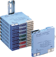
MTL5000 Range
Brand: MTL InstrumentsMTL5000 range of isolators provide intrinsically safe (IS) communication and signal conditioning for a wide range of hazardous-area devices. Total ac and dc isolation exists between input, output and power supply on separately powered units, and between input and output on loop-powered units.
No IS earth is required. DIN-rail mounting and plug-in signal and power connectors simplify installation and maintenance. Units are powered from a 20 to 35V dc supply, or, in some cases, from the signal itself.
1 - 12 of 32 Part Numbers
MTL5011B SWITCH/ PROXIMITY DETECTOR INTERFACE
Number of channels
- One
Location of switch
- Zone 0, IIC, T6 hazardous area
- Div. 1, Group A hazardous location
Location of proximity detector
- Zone 0, IIC, T4–6 hazardous area if suitably certified
- Div. 1, Group A hazardous location
Safe-area output
- One relay with changeover contacts
Hazardous-area input
- Input conforming to NAMUR/DIN 19234 standards for proximity detectors
Voltage applied to sensor
- 7 to 9V from 1kΩ ±10%
Input/output characteristics
- Normal (reverse) phase
- output energised (de-energised) if Iin >2.1mA or Rin <2kΩ
- output de-energised (energised) if Iin 10kΩ
- Hysteresis: 200μA, typical
Line fault detection (LFD)
- User-selectable, via switches on the top of unit. Line faults are
- indicated by an LED. A detected line fault de-energises the relay.
- Open-circuit alarm on if I in <100μA
- Open-circuit alarm off if I in >250μA
- Short-circuit alarm on if Rin <100Ω
- Short-circuit alarm off if Rin >360Ω
- Note: Resistors must be fitted when using the LFD facility with a contact input
- 500Ω to 1kΩ in series with switch
- 20kΩ to 25kΩ in parallel with switch
Phase reversal
- User-selectable, via switches on the top of unit.
Relay type
- Single-pole changeover relay
- Note: reactive loads must be adequately suppressed
Relay characteristics
- Response time: 10ms maximum
- Contact rating: 250V ac, 2A, cosø >0.7
- 40V dc, 2A, resistive load
LED indicators
- Green: power indication
- Yellow: status of channel (on when outputs are energised)
- Red: LFD indication (on when line fault detected)
Maximum current consumption
- 40mA at 20V
- 35mA at 24V
- 25mA at 35V
Maximum power dissipation
- 0.75W at 24V
- 0.8W at 35V
Isolation
- 250V ac or dc between power supply, hazardous-area circuits and relay outputs
Safety description (each channel)
- 10.5V, 800Ω, 14mA, U m = 250V rms or dc
MTL5012 Switch/Proximity Detector Interface
Number of channels
- One
Location of switch
- Zone 0, IIC, T6 hazardous area
- Div. 1, Group A hazardous location
Location of proximity detector
- Zone 0, IIC, T4–6 hazardous area if suitably certified
- Div. 1, Group A hazardous location
Safe-area output
- Floating solid-state output compatible with logic circuits
Hazardous-area input
- Input conforming to NAMUR/DIN 19234 standards for proximity detectors
Voltage applied to sensor
- 7 to 9V from 1kΩ ±10%
Input/output characteristics
- Normal (reverse) phase:
- output on (off) if I in >2.1mA or Rin <2kΩ
- output off (on) if I in 10kΩ
- Hysteresis: 200μA, typical
Line fault detection (LFD)
- User-selectable. Line faults are indicated by an LED. A detected
- line fault switches off the output.
- Open-circuit alarm on if I in <50μA
- Open-circuit alarm off if I in >150μA
- Short-circuit alarm on if Rin <100Ω
- Short-circuit alarm off if Rin >360Ω
- Note: Resistors must be fitted when using the LFD facility with a contact input
- 500Ω to 1kΩ in series with switch
- 20kΩ to 25kΩ in parallel with switch
Phase reversal
- User-selectable
Output characteristics
- Operating frequency: dc to 5kHz
- Max. off-state voltage: 35V
- Max. off-state leakage current: 10μA
- Max. on-state voltage drop: 1 + (0.13 x current in mA) V
- Max. on-state current: 50mA
LED indicators
- Green: power indication
- Yellow: status (on when output is on)
- Red: LFD indication (on when line fault detected)
Maximum current consumption
- 28mA at 20V
- 30mA at 24V
- 32mA at 35V
Maximum power dissipation
- 0.8W at 24V
- 1.2W at 35V
Isolation
- 250V ac or dc between power supply, input and output
Safety description
- 10.5V, 800Ω, 14mA, U m = 250V rms or dc
MTL5012S
Number of channels
- One
Location of switch
- Zone 0, IIC, T6 hazardous area
- Div. 1, Group A hazardous location
Location of sensor
- Zone 0, IIC, T4–6 hazardous area if suitably certified
- Div. 1, Group A hazardous location
Safe-area output
- Floating solid-state output compatible with logic circuits
Hazardous-area input
- Designed to match United Electric One series 2-wire sensors
Voltage applied to sensor
- 7 to 9V from 500Ω ±10%
Input/output characteristics
- Normal (reverse) phase:
- output on (off) if I in >3.8mA or Rin <1.3kΩ
- output off (on) if I in 3.1kΩ
- Hysteresis: 0.5mA, typical
Line fault detection (LFD)
- User-selectable. Line faults are indicated by an LED. A detected
- line fault switches off the output.
- Open-circuit alarm on if I in <50μA
- Open-circuit alarm off if I in >150μA
- Short-circuit alarm on if Rin <100Ω
- Short-circuit alarm off if Rin >360Ω
- Note: Resistors must be fitted when using the LFD facility with a contact input
- 500Ω to 1kΩ in series with switch
- 20kΩ to 25kΩ in parallel with switch
Phase reversal
- User-selectable
Output characteristics
- Operating frequency: dc to 5kHz
- Max. off-state voltage: 35V
- Max. off-state leakage current: 10μA
- Max. on-state voltage drop: 1 + (0.13 x current in mA) V
- Max. on-state current: 50mA
LED indicators
- Green: power indication
- Yellow: status (on when output is on)
- Red: LFD indication (on when line fault detected)
Maximum current consumption
- 33mA at 20V
- 35mA at 24V
- 38mA at 35V
Maximum power dissipation
- 0.9W at 24V
- 1.4W at 35V
Isolation
- 250V ac or dc between power supply, input and output
Safety description
- 10.5V, 480Ω, 22mA, U m = 250V rms or dc
MTL5014 Switch/Proximity Detector Interface
Number of channels
- One
Location of switches
- Zone 0, IIC, T6 hazardous area
- Div. 1, Group A hazardous location
Location of proximity detectors
- Zone 0, IIC, T4–6 hazardous area if suitably certified
- Div. 1, Group A hazardous location
Safe-area output
- Two relays with changeover contacts
Hazardous-area input
- One input conforming to NAMUR/DIN 19234 standards for proximity detectors
Voltage applied to sensor
- 7.0 to 9.0V from 1kΩ ±10%
Input/output characteristics
- Normal (reverse) phase
- output energised (de-energised) if I in >2.1mA or Rin <2kΩ
- output de-energised (energised) if I in <1.2mA or Rin <10kΩ
- Hysteresis: 250μA typical
Phase reversal
- User selectable
Relay type
- Single pole, changeover contacts
- Note: reactive loads must be adequately suppressed
Relay characteristics
- Response time: 10ms maximum
- Contact rating: 250V ac, 2A, cosø >0.7
- 40V dc, 2A, resistive load
- Contact life expectancy: 3 x 10 5 operations at maximum load
Line fault detection (LFD)
- User selectable: Off or On
- A detected line fault de-energises Output 1 relay
- Open circuit alarm on if Iin< 100μA
- Short circuit alarm on if Iin > 6.5mA
- Note: For contact input, resistors must be fitted
- 500Ω to 1kΩ in series with switch
- 20kΩ to 25kΩ in parallel with switch
Output 2 mode
- User selectable: Slave or LFD mode
- In LFD mode, a line fault de-energises Output 2 relay
- Open circuit alarm on if Iin < 100μA
- Short circuit alarm on if Iin > 6.5mA
- See note above on use of resistors
- In Slave mode output 2 repeats output 1
Power supply failure protection
- Relays de-energised if supply fails
LED indicators
- Green: power indication
- Yellow: illuminated when output 1 is energised
- Red: illuminated when LFD is selected and there is an open or short circuit in the field wiring
Supply voltage
- 20 to 35V dc
Maximum current consumption
- 45mA at 24V
- 50mA at 20V
- 35mA at 35V
Maximum power dissipation within unit
- 1.1W at 24V
- 1.3W at 35V
Safety description
- 10.5V, 800Ω, 14mA, U m = 250V rms or dc
MTL5015 Switch/Proximity Detector Interface
Number of channels
- Two
Location of switches
- Zone 0, IIC, T6 hazardous area
- Div. 1, Group A hazardous location
Location of proximity detectors
- Zone 0, IIC, T4–6 hazardous area if suitably certified
- Div. 1, Group A hazardous location
Safe-area outputs
- Floating solid-state outputs compatible with logic circuits
Hazardous-area inputs
- Inputs conforming to NAMUR/DIN 19234 standards for proximity detectors
Voltage applied to sensor
- 7 to 9V from 1kΩ ±10%
Input/output characteristics
- Normal (reverse) phase
- output on (off) if I in >2.1mA or Rin <2kΩ
- output off (on) if I in 10kΩ
- Hysteresis: 200μA, typical
Line fault detection (LFD)
- User-selectable. Line faults are indicated by an LED for each
- channel. A detected line fault switches off the output.
- Open-circuit alarm on if I in <50μA
- Open-circuit alarm off if I in >150μA
- Short-circuit alarm on if Rin <100Ω
- Short-circuit alarm off if Rin >360Ω
- Note: Resistors must be fitted when using the LFD facility with a contact input
- 500Ω to 1kΩ in series with switch
- 20kΩ to 25kΩ in parallel with switch
Phase reversal
- Independent for each channel, user-selectable
Output characteristics
- Operating frequency: dc to 5kHz
- Max. off-state voltage: 35V
- Max. off-state leakage current: 10μA
- Max. on-state voltage drop: 1 + (0.13 x current in mA) V
- Max. on-state current: 50mA
LED indicators
- Green: power indication
- Yellow: two: status of each channel (on when outputs are on)
- Red: two: LFD indication for each channel (on when line fault detected)
Maximum current consumption
- 42mA at 20V
- 44mA at 24V
- 46mA at 35V
Maximum power dissipation
- 1.1W at 24V
- 1.6W at 35V
Isolation
- 250V ac or dc between power supply, hazardous-area circuits
- and each output. 30V between hazardous-area circuits.
Safety description (each channel)
- 10.5V, 800Ω, 14mA, U m = 250V rms or dc
MTL5017 Switch/Proximity Detector Interface
Number of channels
- Two
Location of switches
- Zone 0, IIC, T6 hazardous area
- Div. 1, Group A hazardous location
Location of proximity detectors
- Zone 0, IIC, T4–6 hazardous area if suitably certified
- Div. 1, Group A hazardous location
Safe-area output
- Two relays with normally-open contacts signal status of input
- An additional relay signals line faults
Hazardous-area input
- Two inputs conforming to NAMUR/DIN 19234 standards for proximity detectors
- Resistors must be fitted externally to contact inputs: 500Ω to 1kΩ in series with the switch, 20kΩ to 25kΩ in parallel with the switch.
Voltage applied to sensor
- 7.0 to 9.0V from 1kΩ ±10%
Output characteristics
- Normal (reverse) phase
- output relay closed (open) if I in >2.1mA or Rin <2kΩ
- output relay open (closed) if I in 10kΩ
- Hysteresis: 250μA typical
Line fault detection (LFD)
- Line faults are indicated by an LED and a safe-area relay. When a line fault is detected, the relay opens and the LED lights.
- Open-circuit alarm on if I in <100μA
- Open-circuit alarm off if I in >250μA
- Short-circuit alarm on if Rin <100Ω
- Short-circuit alarm off if Rin >360Ω
- Note: For contact input, resistors must be fitted
- 500Ω to 1kΩ in series with switch
- 20kΩ to 25kΩ in parallel with switch
Phase reversal
- Independent on each channel, selected by switches on the base of the unit
Relay type
- Single-pole, normally-open contacts.
- Note: reactive loads must be adequately suppressed.
Relay characteristics
- Response time: 2ms maximum
- Contact rating: 10VA, 45mA, 250V ac
- 10W, 0.5A, 220V dc
- 10W, 0.5A, 220V dc
- Contact life expectancy: 10 7 operations at maximum load
LED indicators
- Green: power indication
- Yellow: two: status of each channel, on when output relay is closed
- Red: two: line fault detected in channel 1/channel 2
Supply voltage
- 20 to 35V dc
Maximum current consumption
- 50mA at 24V
- 55mA at 20V
- 40mA at 35V
Maximum power dissipation within unit
- 1.1W at 24V
- 1.25W at 35V
Safety description (each channel)
- 10.5V, 800Ω, 14mA, U m = 250V rms or dc
MTL5018 Switch/Proximity Detector Interface
Number of channels
- Two
Location of switches
- Zone 0, IIC, T6 hazardous area
- Div. 1, Group A hazardous location
Location of proximity detector
- Zone 0, IIC, T4–6 hazardous area if suitably certified
- Div. 1, Group A hazardous location
Safe-area output
- Two relays with changeover contacts
Hazardous-area inputs
- Inputs conforming to NAMUR/DIN 19234 standards for proximity detectors
Voltage applied to sensor
- 7 to 9V from 1kΩ ±10%
Input/output characteristics
Normal (reverse) phase:
output energised (de-energised) if Iin >2.1mA or Rin <2kΩ
output de-energised (energised) if Iin 10kΩ
Hysteresis: 200μA, typical
Line fault detection (LFD)
- User-selectable via switches on the top of the unit. Line faults are indicated by an LED for each channel. A detected line fault de-energises the relay.
- Open-circuit alarm on if I in <100μA
- Open-circuit alarm off if I in >250μA
- Short-circuit alarm on if Rin <100Ω
- Short-circuit alarm off if Rin >360Ω
- Note: Resistors must be fitted when using the LFD facility with a contact input
- 500Ω to 1kΩ in series with switch
- 20kΩ to 25kΩ in parallel with switch
Phase reversal
- Independent for each channel, user-selectable
Relay type
- Single pole, changeover contacts
- Note: reactive loads must be adequately suppressed
Relay characteristics
- Response time: 10ms maximum
- Contact rating: 250V ac, 2A, cosø >0.7
- 40V dc, 2A, resistive load
LED indicators
- Green: power indication
- Yellow: two: status of each channel (on when outputs are energised)
- Red: two: LFD indication for each channel (on when line fault detected)
Maximum current consumption
- 60mA at 20V
- 60mA at 24V
- 40mA at 35V
Maximum power dissipation
- 1.4W at 24V
- 1.5W at 35V
Isolation
- 250V ac or dc between power supply, hazardous-area circuits and relay outputs
Safety description (each channel)
- 10.5V, 800Ω, 14mA, U m = 250V rms or d
MTL5018AC SWITCH/ PROXIMITY DETECTOR INTERFACE
Number of channels
- Two
Location of switches
- Zone 0, IIC, T4–6 hazardous area
- Div. 1, Group A hazardous location
Safe-area output
- Two relays with changeover contacts
Hazardous-area inputs
- Inputs conforming to NAMUR/DIN 19234 standards for proximity detectors
Voltage applied to sensor
- 7 to 9V from 1kΩ ±10%
Input/output characteristics
- Normal (reverse) phase
- output energised (de-energised) if Iin >2.1mA or Rin <2kΩ
- output de-energised (energised) if Iin 10kΩ
- Hysteresis: 200μA, typical
Line fault detection (LFD)
- User-selectable via switches on the top of the unit. Line faults are indicated by an LED for each channel. A detected line fault de-energises the relay.
- Open-circuit alarm on if Iin <100μA
- Open-circuit alarm off if Iin >250μA
- Short-circuit alarm on if Rin <100Ω
- Short-circuit alarm off if Rin >360Ω
- Note: Resistors must be fitted when using the LFD facility with a contact input
- 500Ω to 1kΩ in series with switch
- 20kΩ to 25kΩ in parallel with switch
Phase reversal
- Independent for each channel, user-selectable
Relay type
- Single pole, changeover contacts
- Note: reactive loads must be adequately suppressed
Relay characteristics
- Response time: 10ms maximum
- Contact rating: 250V ac, 2A, cosø >0.7
- 40V dc, 2A, resistive load
LED indicators
- Green: power indication
- Yellow: two: status of each channel (on when outputs are energised)
- Red: two: LFD indication for each channel (on when line fault detected)
Maximum power dissipation
- <2.5W
Isolation
- 250V ac or dc between power supply, hazardous-area circuits and relay outputs
Safety description (each channel)
- 10.5V, 800Ω, 14mA, Um= 250V rms or dc
Power Supply
- 85 to 265V ac
- 45 to 65 Hz
MTL5021 Solenoid/Alarm Driver
Number of channels
- One
Location of load
- Zone 0, IIC, T4–-6 hazardous area if suitably certified
- Div. 1, Group A hazardous location
LED indicator
- Yellow: status
Input voltage
- 20 to 35V dc
Hazardous-area output
- Minimum output voltage: 12.85V at 45mA
- Maximum output voltage: 24V from 170Ω
- Current limit: 45mA
Maximum current consumption (with 45mA output)
- 90mA at 24V
- 110mA at 20 to 35V dc
Maximum power dissipation within unit
- 1.4W at 24V typical
- 1.8W at 35V maximum
Safety description
- 25V, 170Ω, 147mA, U m = 250V rms or dc
MTL5022 Solenoid/Alarm Driver
Number of channels
- One
Location of load
- Zone 0, IIB, T4–6 hazardous area if suitably certified
- Div. 1, Group C hazardous location
LED indicator
- Yellow: status
Input voltage
- 20 to 35V dc
Hazardous-area output
- Minimum output voltage: 12.9V at 60mA
- Maximum output voltage: 24V from 133Ω
- Current limit: 60mA
Maximum current consumption (with 60mA output)
- 115mA at 24V, typical
- 135mA at 20 to 35V dc, maximum
Maximum power dissipation within unit
- 1.5W at 24V
- 2.1W at 35V
Safety description
- 25V, 135Ω, 185mA, U m = 250V rms or dc
MTL5023 Solenoid/Alarm Driver
Number of channels
- One
Location of load
- Zone 0, IIC, T4–6 hazardous area if suitably certified
- Div. 1, Group A hazardous location
Hazardous-area output
- Minimum voltage: 12.85V at 45mA
- Maximum voltage: 25V
- Current limit : 45mA
Output ripple
- 100mV peak-to-peak maximum
Control input
- Normal (reverse) phase
- Output turns on (off) if input switch closed, transistor on or <1.4V applied across terminals 12 and 11
- Output turns off (on) if input switch open, transistor off or >4.5V applied across terminals 12 and 11
Output response time
- Within 10% of final value within 50ms
Line fault detection
- Open or short circuit in the field de-energises solid-state line-fault signal.
- No line fault will be signalled while the field-circuit impedance stays within the range 50Ω to 7kΩ.
Line fault signal characteristics
- Maximum off-state voltage: 35V
- Maximum off-state leakage current: 10μA
- Maximum on-state voltage drop: [1 + (0.08 x current in mA)] V
- Maximum on-state current: 50mA
Phase reversal
- Selected via a switch on the base of the module
LED indicator
- Green: power indication
- Yellow: status, on when output circuit is active
- Red: line fault detected
Supply voltage
- 20 to 35V dc
Maximum current consumption
- 100mA at 24V
- 120mA at 20V
- 80mA at 35V
Maximum power dissipation within unit
- 1.4W with typical solenoid valve, output on
- 2.0W worst case
Safety description
- 25V, 170Ω, 147mA, U m = 250V rms or dc
MTL5024 Solenoid/Alarm Driver
Number of channels
- One
Location of load
- Zone 0, IIC, T4–6 hazardous location if suitably certified
- Div. 1, Group A hazardous location
Safe-area input
- Suitable for switch contacts, an open-collector transistor or logic drive.
- Normal (reverse) phase: output on (off) if switch closed
- transistor on or <1.4V applied to input
- output off (on) if switch open
- transistor off or >4.5V applied to input
- Hazardous-area output
- Minimum output voltage: 12.85V at 45mA
- Maximum output voltage: 25V
- Current limit : 45mA
Phase reversal
- Selected by a switch on the base of the module
LED indicators
- Green: power indication
- Yellow: status
Supply voltage
- 20 to 35V dc
Maximum current consumption
- 100mA at 24V
- 120mA at 20V dc
- 75mA at 35V dc
Maximum power dissipation within unit
- 1.4W with typical solenoid valve, output on
- 2.0W worst case
Safety description
- 25V, 170Ω, 147mA, Um = 250V rms or dc
1 - 12 of 32 Part Numbers
Specifications
Brand
Connectors
- Each MTL5000 unit is supplied with signal and power connectors, as applicable
- When using crimp Ferrules for the hazardous and Non-hazardous (safe) signal Connectors the metal Tube length should be 12 mm and the wire trim length 14 mm. for the Power Connectors the metal Tube length should be 10 mm and the wire trim length 12 mm.
- See INM5000 for recommended Ferrules
Isolation
- 250 V RMS between Input, output and Power Supply terminals, tested at 1500 V RMS minimum between safe- and hazardous-area terminals. MTL5073, output and Power Supply not isolated
Location of Units
- Safe Area
Terminals
- Accommodate conductors of up to 2.5 mm 2 stranded or single- core
Mounting
- On 35 mm (Top hat) Rail to: EN 50022-35 x 7.5, BS 5584, 35 x 27 x 7.3 DIN 46277
Ambient Temperature Limits
- -20° to +60° C (-6° to +140° F) operating
- -40° to +80° C (-40° to +176° F) storage
Humidity
- 5 to 95 % Relative Humidity
Weight
- 110 g approx (Except where indicated)
Documentation
Data Sheets
- EPS MTL5018AC Rev 3 Data Sheet pdf 68 KB
- EPS MTL5053 Data Sheet pdf 101 KB
- INM5000 Data Sheet pdf 539 KB
- MTL5000 Accessories pdf 117 KB
- MTL5011B Data Sheet pdf 67 KB
- MTL5012 Data Sheet pdf 70 KB
- MTL5012S Data Sheet pdf 70 KB
- MTL5014 Data Sheet pdf 71 KB
- MTL5015 Data Sheet pdf 68 KB
- MTL5017 Data Sheet pdf 72 KB
- MTL5018 Data Sheet pdf 49 KB
- MTL5021 Data Sheet pdf 62 KB
- MTL5022 Data Sheet pdf 62 KB
- MTL5023 Data Sheet pdf 65 KB
- MTL5024 Data Sheet pdf 64 KB
- MTL5025 Data Sheet pdf 62 KB
- MTL5031 Data Sheet pdf 56 KB
- MTL5032 Data Sheet pdf 59 KB
- MTL5040 Data Sheet pdf 64 KB
- MTL5041 Data Sheet pdf 62 KB
- MTL5042 Data Sheet pdf 70 KB
- MTL5043 Data Sheet pdf 63 KB
- MTL5044 Data Sheet pdf 63 KB
- MTL5045 Data Sheet pdf 61 KB
- MTL5046 Data Sheet pdf 62 KB
- MTL5049 Data Sheet pdf 61 KB
- MTL5061 Data Sheet pdf 72 KB
- MTL5074 Data Sheet pdf 82 KB
- MTL5081 Data Sheet pdf 36 KB
- MTL5082 Data Sheet pdf 59 KB
- MTL5099 Data Sheet pdf 51 KB
- MTL5113P Data Sheet pdf 69 KB
- MTL5344 Data Sheet pdf 63 KB
- MTL5349 Data Sheet pdf 61 KB