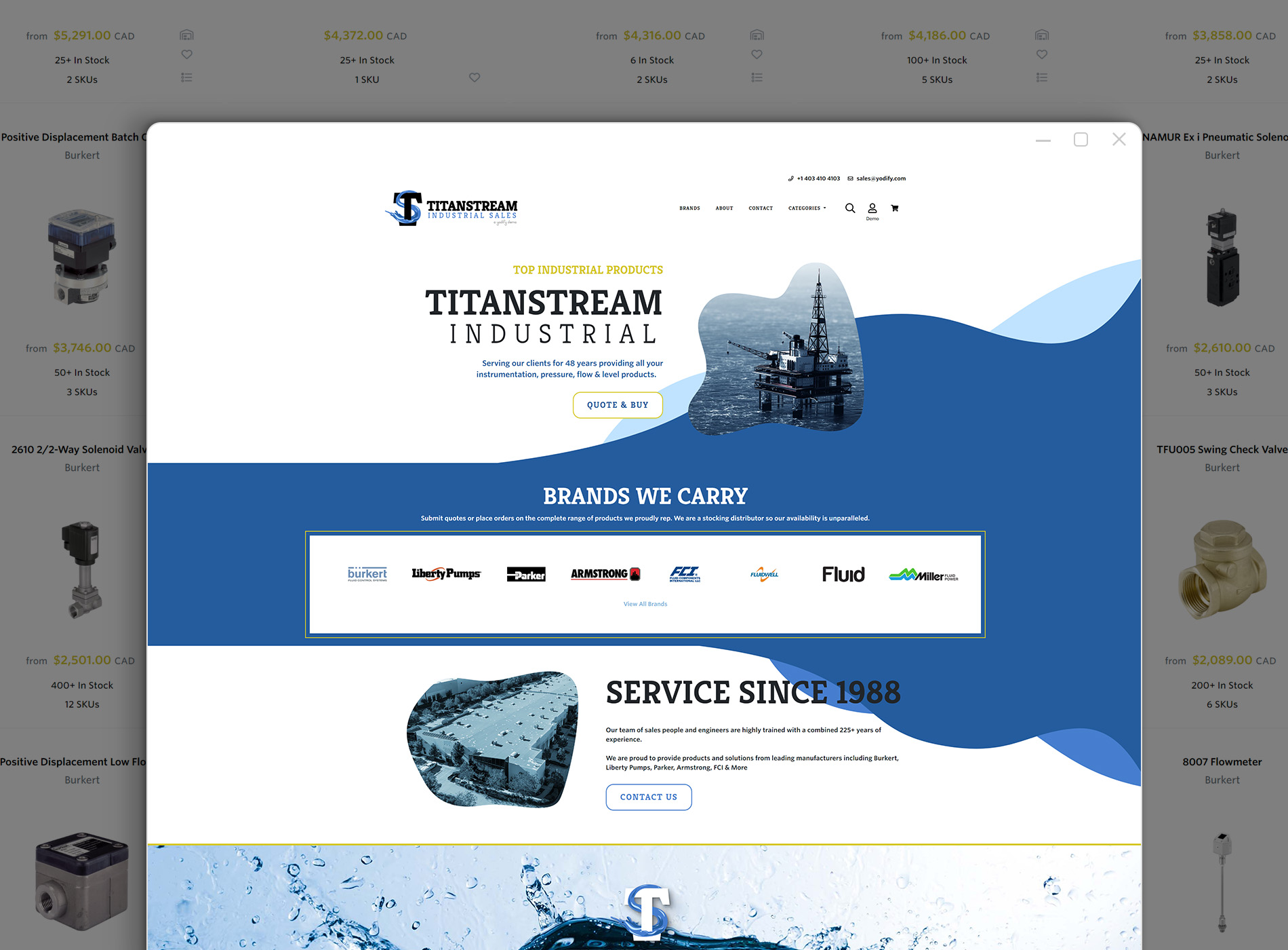
Yodify Product Library
Add the Eclipse® 700 Guided Wave Radar Transmitter to your store or catalog
Book Your Demo and See How
or create your store
Eclipse® 700 Guided Wave Radar Transmitter
Brand: MagnetrolThe Eclipse® Model 700 Transmitter is a loop-powered, 24 VDC level transmitter that is based upon the proven and accepted technology of Guided Wave Radar (GWR).
Encompassing a number of significant engineering accomplishments, this leading-edge level transmitter is designed to provide measurement performance well beyond that of many of the more traditional technologies.
This single transmitter can be used in a wide variety of applications ranging from very light hydrocarbons to water-based media.
One universal Model 700 transmitter can be used and interchanged with several different probe types and offers enhanced reliability as it is certified for use in critical SIL 2/3 hardware safety loops.
The ECLIPSE Model 700 supports both the FDT/DTM and Enhanced DD (EDDL) standards, which allow viewing of valuable configuration and diagnostic information such as the echo curve in tools such as PACTware™, AMS Device Manager, and various HART® Field Communicators.
Technology - Guided Wave Radar
Micropower impulse radar combines time domain reflectometry, equivalent time sampling, and modern low power circuitry. This synthesis of technologies creates a high-speed Guided Wave Radar transmitter.
The electromagnetic pulses are propagated via a waveguide that focuses the energy and yields a system many times more efficient than Non-Contact Radar.
Guided Wave Radar Probes
Choosing the proper guided wave radar (GWR) probe is the most important decision in the application process. The probe configuration establishes fundamental performance characteristics.
Coaxial and single element (rod or cable) are the two basic configurations used today, each with specific strengths and weaknesses.
Single element GWR probes act quite differently from coaxial designs.
The pulses of energy develop between the center rod and the mounting nut or flange; the pulse propagates down the rod as it references its ground at the top of the tank.
The efficiency of the pulse "launch" is directly related to how much metallic surface exists around it at the top of the vessel.
Signal transmission can be significantly improved by placing a single rod inside of a bridle or chamber.
Operating Principle
ECLIPSE Guided Wave Radar is based upon the technology of TDR (Time Domain Reflectometry). TDR utilizes pulses of electromagnetic energy transmitted down a wave guide (probe).
When a pulse reaches a surface that has a higher dielectric constant than the air (εr = 1) in which it is traveling, a portion of the pulse is reflected.
The transit time of the pulse is then measured via high speed timing circuitry that provides an accurate measure of the liquid (or solids) level.
The amplitude of the reflection depends on the dielectric constant of the product. The higher the dielectric constant, the larger is the reflection.
Features- Multivariable, two-wire, 24 VDC loop-powered transmitter for level, interface, volume, or flow
- Level measurement not affected by changing media characteristics
- No need to move levels for calibration
- Overfill Capable probes allow for “true level” measurement all the way up to the process seal, without the need for special algorithms
- 4-button keypad and graphic LCD display allow for convenient viewing of configuration parameters and echo curve
- Proactive diagnostics advise not only what is wrong, but also offer troubleshooting tips
- Options
- Nine common tank shapes for volumetric output
- 30-point custom strapping table for uncommonly shaped tanks
- Two standard flumes and four standard weirs of various sizes for flow measurement
- Generic flow equation for non-standard channels
- Probe designs up to +200°C/431 bar (+400°F/ 6250 psi)
- Cryogenic applications down to -196°C (-320°F)
- SIL certification allows use in SIL 2/3 Loops
- No moving parts
Specifications
Brand
Approvals
- ATEX
- IEC
- FM US/Canada
- SIL
System Design
- Measurement Principle: Guided Wave Radar based on Time Domain Reflectometry (TDR)
Input
- Measured Variable: Level, as determined by GWR time of flight
- Span: 6 inches to 100 ft (15 cm to 30 m)
Output
- Type: 4-20 mA with HART: 3.8 mA to 20.5 mA useable (per NAMUR NE43)
- Resolution: Analog: 0.003 mA | Digital Display: 1 mm
- Loop Resistance: 590 ohms @ 24 Vdc and 22 mA
- Diagnostic Alarm - Selectable: 3.6 mA, 22 mA (meets requirements of NAMURNE43), or HOLD last output
- Diagnostic Indication: Meets requirements of NAMUR NE107
- Damping: Adjustable 0-10 seconds
User Interface
- Keypad: 4-button Menu-driven Data Entry
- Display: Graphic Liquid Crystal Display
- Digital Communication/Systems: HART Version 7—with Field Communicator, AMS, or FDT | DTM (PACTware™), EDDL
- Menu Languages - Transmitter LCD: English, French, German, Spanish, Russian | HART DD: English, French, German, Spanish, Russian, Chinese, Portuguese, Polish
Power (At Transmitter Terminals)
- 11 Vdc Min. under Certain Conditions (Refer to I&O Manual 57-660)
Housing
- Material: IP67/Die-Cast Aluminum A413 (< 0.6 % Copper)
- Net/Gross Weight - Aluminum: 4 lb (1.8 kg)
- Overall Dimensions: H 5.41" (137 mm) x W 4.86" (123 mm) x D 4.55" (116 mm)
- Cable Entry: 1/2" NPT or M20
- SIL 2/3 Capable (Certified): Safe Failure Fraction = 92.4 % (HART only) | Functional Safety to SIL 2/3 in accordance with IEC 61508
Environment
- Operating Temperature: -40 to +175° F (-40 to +80° C), LCD Viewable -5 to +160° F (-20 to +70° C
- Storage Temperature: -50 to +185° F (-45 to +85° C)
- Humidity: 0 to 99 %, Non-Condensing
- Electromagnetic Compatibility: Meets CE Requirement (EN 61326) and NAMUR NE 21*
- *Single rod probes must be used in metallic vessel or still well to maintain CE noise immunity
- Surge Protection: Meets CE EN 61326 (1000 V)
- Shock/Vibration: ANSI / ISA-S71.03 Class SA1 (Shock), ANSI / ISA-S71.03 Class VC2 (Vibration)
Performance
- Reference Conditions: Reflection from Liquid, with Dielectric Constant in Center of Selected range, with a 72" (1.8 m) Coaxial Probe at +70° F (+20° C), in Auto Largest Threshold Mode➀
- Linearity: Coaxial, Single Rod Rigid/Cable: < 0.1 % of Probe Length or 0.1 inch (2.5 mm), whichever is greater➁
- Accuracy - Coaxial, Single Rod Rigid/Cable: ± 0.1 % of Probe Length or ± 0.1 inch (2.5 mm), whichever is greater | Interface Operation: Coaxial: ± 1 inch (25 mm) for an Interface Thickness greater than 2 inches (50 mm)
- Resolution: ± 0.1 inch or 1 mm
- Repeatability: < 0.1 inch (2.5 mm)
- Hysteresis: < 0.1 inch (2.5 mm)
- Response Time: Approximately 1 second
- Initialization Time: Less than 10 seconds
- Ambient Temperature Effect: Approx. ± 0.02 % of Probe Length/degree C (for probes greater than 8 feet (2.5 m))
- Process Dielectric: < 0.3 inch (7.5 mm) within Selected Range
- ➀Specifications will degrade in Fixed Threshold mode
- ➁Linearity in top 18 inches (46 cm) of single rod probes will be application dependent.
- Ammonia Storage
- Blending Operations
- Catalysis Vessels
- Chemical Injection
- Chemical Injection Skids
- Chemical Reactors
- Chlor-Alkali Process
- Condenser
- Deionization Tanks
- Distillation Columns
- Distillation Towers
- Fermentation Vessels
- Heat Recovery Steam Generator (HRSG) - Power/Utilities
- Lime Slurry Level
- Liquid-Liquid Extraction
- Mixing & Blending Systems
- Neutralization
- Quench Tower/Settler
- Reboiler
- Reflux Drum
- Scrubber Vessels
- Seal Pots - Liquid Level Measurement
- Steam Drums for Chemical Industry
- Surge Drums
- Tank Blanketing
- Tank Blanketing in Oil & Gas Field Processing
- Vapor and Liquid Separation
Documentation
Approvals & Certificates
- ATEX Ex i Certificate Eclipse 700 pdf 600 KB
- ATEX Ex n Certificate Eclipse 700 pdf 575 KB
- Canadian Certificate Eclipse® 700 - IS, nA, DIP, NI pdf 330 KB
- FM Certificate Eclipse® 700 - IS, nA, DIP, NI pdf 331 KB
- FMEDA Report Eclipse 700 pdf 714 KB
- IECEx I Certificate Eclipse 700 pdf 123 KB
- IECEx n Certificate Eclipse 700 pdf 123 KB
- SIL 3 Certificate Eclipse 700 pdf 218 KB
Catalogs
- Eclipse® Model 700 (Chinese) pdf 2.7 MB
- Eclipse® Model 700 (English) pdf 696 KB
- Eclipse® Model 700 (French) pdf 1.1 MB
- Eclipse® Model 700 (German) pdf 1.2 MB
- Eclipse® Model 700 (Italian) pdf 1.2 MB
- Eclipse® Model 700 (Portuguese) pdf 1.0 MB
- Eclipse® Model 700 (Russian) pdf 602 KB
- Eclipse® Model 700 (Spanish) pdf 1.2 MB
- Eclipse® Model 700 (US) pdf 1.2 MB
Instruction Manuals
- Eclipse® Model 700 HART (English) pdf 2.6 MB
- Eclipse® Model 700 HART (French) pdf 3.6 MB
- Eclipse® Model 700 HART (German) pdf 3.8 MB
- Eclipse® Model 700 HART (Italian) pdf 3.6 MB
- Eclipse® Model 700 HART (Portuguese) pdf 4.3 MB
- Eclipse® Model 700 HART (Russian) pdf 3.6 MB
- Eclipse® Model 700 HART (Spanish) pdf 3.4 MB
- Eclipse® Model 700 HART (US) pdf 3.4 MB
- Eclipse® Model 700 SIL Safety Manual pdf 642 KB


