

Yodify Product Library
Add the Frequency Transmitter Series 9146 to your store or catalog
Book Your Demo and See How
or create your store

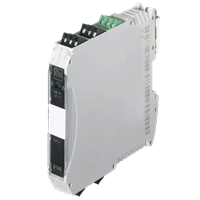
Frequency Transmitter Series 9146
Brand: R. STAHL AG9146 series Ex i- frequency transmitters monitor the speed of rotating parts on one or two channels, e.g. the speed of fans or centrifuges.
The frequency measured at the intrinsically safe input (between 0.001 Hz and 20 kHz) is issued as a unit signal (0/4 mA to 20 mA) or processed by a frequency divider.
In single-channel devices, these frequency transmitters check whether speeds have exceeded or fallen below the limit values.
Features- Compact Ex i frequency transmitter for monitoring rotational speed in hazardous areas
- Limit value analysis + frequency-current conversion + pulse divider function over a width of just 17.6 mm
- Parameterization made easy by "ISpac Wizard" software
1 - 4 of 4 Part Numbers
159883
Compact Ex i frequency transmitter for monitoring rotational speed in hazardous areas
Limit value analysis + frequency-current conversion + pulse divider function over a width of just 17.6 mm
Parameterization made easy by "ISpac Wizard" software
Ambient Conditions
- Ambient temperature - -20 °C ... +70 °C (Single device) -20 °C ... +60 °C (Group assembly)
- Ambient temperature max. - +70 °C
- Ambient temperature max. note - Single device
- Ambient temperature max. note 2 - Group assembly
- Ambient temperature max.2 - +60 °C
- Ambient temperature min. - -20 °C
- Ambient temperature min. 2 - -20 °C
- Ambient temperature min. note - Single device
- Ambient temperature min. note 2 - Group assembly
- Electromagnetic compatibility - Tested to the following standards and regulations: EN 61326-1 Use in industrial environment; NAMUR NE 21
- Relative humidity max. - 95%
- Storage temperature - -40 °C ... +80 °C
- Storage temperature max. - +80 °C
- Storage temperature min. - -40 °C
- Use at the height of - < 2000 m
Auxiliary power
- Auxiliary power - 24 V DC
- Auxiliary power voltage range - 18 ... 31,2 V
- Nominal current - 55.00 mA
- Operation indication - Green "PWR" LED
- Polarity reversal protection - yes
- Power consumption - 1.32 W
- Power dissipation max. - 1.10 W
- Undervoltage monitoring - Yes
- Voltage range residual ripple - ≤ 3,6 VSS
Electrical Data
- Number of channels - 1
Explosion Protection
- Application range (zones) - 2, 22
- ATEX dust certificate - BVS 05 ATEX E 0171 X
- ATEX firedamp certificate - BVS 05 ATEX E 0171 X
- ATEX gas certificate - BVS 05 ATEX E 0171 X
- Certificate EAC - TS RU S-DE.GB04.B.00132
- Certificates - ATEX (BVS), Canada (FM), EAC (STV), IECEx (BVS), India (PESO), USA (FM)
- Dust explosion protection ATEX - II (1) D [Ex ia Da] IIIC
- Dust explosion protection EAC - [Ex ia Da] IIIC
- Dust explosion protection IECEx - [Ex ia Da] IIIC
- Ex interface in Division NEC 500 - (Class I, II, III) 1, 2
- Ex interface zone - 0, 1, 2, 20, 21, 22
- Firedamp protection ATEX - I (M1) [Ex ia Ma] I
- Firedamp protection IECEx - [Ex ia Ma] I
- Gas explosion protection ATEX - II 3 (1) G Ex nA nC [ia Ga] IIC T4 Gc
- Gas explosion protection EAC - 2 Ex nA nC [ia Ga] IIC T4 Gc X
- Gas explosion protection IECEx - Ex nA nC [ia Ga] IIC T4 Gc
- IECEX dust certificate - IECEx BVS 13.0095 X
- IECEx firedamp certificate - IECEx BVS 13.0095 X
- IECEX gas certificate - IECEx BVS 13.0095 X
- Installation in Division NEC 500 - (Class I, II, III) 2
- Ship approval - CCS, DNVGL
Galvanic isolation
- Galvanic isolation Ex i input to auxiliary power - 1.5 kV AC
- Galvanic isolation Ex i input to fault message contact - 1,5 kV AC
- Galvanic isolation Ex i input to output - 1.5 kV AC
- Galvanic isolation fault message contact to auxiliary power - 350 V AC
- Galvanic isolation fault message contact to output - 350 V AC
- Galvanic isolation output to auxiliary power - 350 V AC
- Galvanic isolation output to output - 350 V AC
- Test voltage according to standard - IEC EN 60079-11
- Test voltage according to standard 2 - EN 50178
General
- Functional Description - 9146 series Ex i- frequency transmitters monitor the speed of rotating parts on one or two channels, e.g. the speed of fans or centrifuges. The frequency measured at the intrinsically safe input (between 0.001 Hz and 20 kHz) is issued as a unit signal (0/4 mA to 20 mA) or processed by a frequency divider. In single-channel devices, these frequency transmitters check whether speeds have exceeded or fallen below the limit values.
- Highlights - Compact Ex i frequency transmitter for monitoring rotational speed in hazardous areas Limit value analysis + frequency-current conversion + pulse divider function over a width of just 17.6 mm Parameterization made easy by "ISpac Wizard" software
- Product Description - Frequency transmitter Ex i field circuit
- Product Type - 9146/10-11-12s
- Title Product Variant Technical Data - Number of channels 1
- WebCode - 9146A
Input
- hysteresis - ca. 0,2 mA
- input current for OFF - ≤ 1,2 mA
- input current for ON - ≥ 2,1 mA
- Input frequency - 0.0010 - 20000.0000 Hz
- Input internal resistiance R i - 1000.00 Ω
- input signal - In accordance with EN 60947-5-6 (NAMUR)
- Message of line fault and Auxilliary power failure - - Contact (30 V / 100 mA) closed to ground in case of fault - pac-Bus, floating contact (30 V / 100 mA)
- short-circuit current - ≤ 8,5 mA
Mechanical Data
- Connection cross-section - 0.2-2.5 mm² flexible 0.2-2.5 mm² rigid 0.25-2.5 mm² flexible core end sleeve
- Degree of protection (IP) - IP30
- Enclosure material - Polyamide
- Fire resistance (UL 94) - V0
- Grid dimension - 17.60 mm
- Terminal degree of protection (IP) - IP20
- Weight - 0.125 kg
Mounting / Installation
- Conduct cross-section flexible max. - 0.2 mm²
- Conduct cross-section flexible max. - 2.5 mm²
- Conductor cross-section solid max. - 2.5 mm²
- Conductor cross-section solid min. - 0.2 mm²
- Connection type - Screw terminal
- Mounting position - vertical horizontal
- Mounting type - NS35/15, NS35/7.5 DIN rail
Output
- Average measurement fault - ≤ 0,1%
- Behaviour of the output - Configurable, factory setting
- Behaviour of the output note - SC: 3,8 mA, OC: 20,5 mA
- Error detection wire breakage - IE < 0.05 ... 0.35 mA
- Frequency range pulse OUT - 0 ... 5 kHz
- Indication of line fault - "LF" LED, red
- Input medium resolution note - < 0.1 % of measuring range
- LFD relay - Yes
- Limit contact (per channel) - 2 NO / NC
- Load resistance R L max. - 600.00 Ω
- Min. pulse duration (ON / OFF) - 25 µs
- Output current max. - 20.50 mA
- Output functional range - 0.0 - 20.5 mA
- Output per channel 1 - 0/4 to 20 mA
- output signal - 0/4 - 20 mA
- Pulse output - One configurable NO
- Short circuit error detection - RE < 100 ... 360 Ω
- Splitting ratio IN / OUT - 1:2 ... 1:20000
- Switch user adjustment line fault - activated / deactivated
- Switch-on resistance - ≤ 12.5 ohms (typical < 9.5 ohms)
- Switching capacity fault message contact - 30 V / 100 mA
- Switching current limiting values - ≤ ± 50 mA
- Switching state indication - Yellow LED "OUT" disconnection
- Switching voltage limiting values - ≤ ± 30 V
- Temperature influence - ≤ 0,05% / 10 K
Safety Data
- Internal capacitance C i - negligible
- Internal inductance L i - negligible
- Max. Current I o - 23.4 mA
- Max. permissible external capacitance C o for I - 95.000 μF
- Max. permissible external capacitance C o for IIA - 75.000 μF
- Max. permissible external capacitance C o for IIB - 16.800 μF
- Max. permissible external capacitance C o for IIC - 2.420 μF
- Max. permissible external inductance L o for I - 600.00 mH
- Max. permissible external inductance L o for IIA - 450.00 mH
- Max. permissible external inductance L o for IIB - 230.000 mH
- Max. permissible external inductance L o for IIC - 63.000 mH
- Max. Power P o - 61.400 mW
- Max. Voltage U o - 10.50 V
- Safety-related maximum voltage - 253 V
159884
Compact Ex i frequency transmitter for monitoring rotational speed in hazardous areas
Limit value analysis + frequency-current conversion + pulse divider function over a width of just 17.6 mm
Parameterization made easy by "ISpac Wizard" software
Ambient Conditions
- Ambient temperature - -20 °C ... +70 °C (Single device) -20 °C ... +60 °C (Group assembly)
- Ambient temperature max. - +70 °C
- Ambient temperature max. note - Single device
- Ambient temperature max. note 2 - Group assembly
- Ambient temperature max.2 - +60 °C
- Ambient temperature min. - -20 °C
- Ambient temperature min. 2 - -20 °C
- Ambient temperature min. note - Single device
- Ambient temperature min. note 2 - Group assembly
- Electromagnetic compatibility - Tested to the following standards and regulations: EN 61326-1 Use in industrial environment; NAMUR NE 21
- Relative humidity max. - 95%
- Storage temperature - -40 °C ... +80 °C
- Storage temperature max. - +80 °C
- Storage temperature min. - -40 °C
- Use at the height of - < 2000 m
Auxiliary power
- Auxiliary power - 24 V DC
- Auxiliary power voltage range - 18 ... 31,2 V
- Nominal current - 55.00 mA
- Operation indication - Green "PWR" LED
- Polarity reversal protection - yes
- Power consumption - 1.32 W
- Power dissipation max. - 1.10 W
- Undervoltage monitoring - Yes
- Voltage range residual ripple - ≤ 3,6 VSS
Electrical Data
- Number of channels - 1
Explosion Protection
- Application range (zones) - 2, 22
- ATEX dust certificate - BVS 05 ATEX E 0171 X
- ATEX firedamp certificate - BVS 05 ATEX E 0171 X
- ATEX gas certificate - BVS 05 ATEX E 0171 X
- Certificate EAC - TS RU S-DE.GB04.B.00132
- Certificates - ATEX (BVS), Canada (FM), EAC (STV), IECEx (BVS), India (PESO), USA (FM)
- Dust explosion protection ATEX - II (1) D [Ex ia Da] IIIC
- Dust explosion protection EAC - [Ex ia Da] IIIC
- Dust explosion protection IECEx - [Ex ia Da] IIIC
- Ex interface in Division NEC 500 - (Class I, II, III) 1, 2
- Ex interface zone - 0, 1, 2, 20, 21, 22
- Firedamp protection ATEX - I (M1) [Ex ia Ma] I
- Firedamp protection IECEx - [Ex ia Ma] I
- Gas explosion protection ATEX - II 3 (1) G Ex nA nC [ia Ga] IIC T4 Gc
- Gas explosion protection EAC - 2 Ex nA nC [ia Ga] IIC T4 Gc X
- Gas explosion protection IECEx - Ex nA nC [ia Ga] IIC T4 Gc
- IECEX dust certificate - IECEx BVS 13.0095 X
- IECEx firedamp certificate - IECEx BVS 13.0095 X
- IECEX gas certificate - IECEx BVS 13.0095 X
- Installation in Division NEC 500 - (Class I, II, III) 2
- Ship approval - CCS, DNVGL
Galvanic isolation
- Galvanic isolation Ex i input to auxiliary power - 1.5 kV AC
- Galvanic isolation Ex i input to fault message contact - 1,5 kV AC
- Galvanic isolation Ex i input to output - 1.5 kV AC
- Galvanic isolation fault message contact to auxiliary power - 350 V AC
- Galvanic isolation fault message contact to output - 350 V AC
- Galvanic isolation output to auxiliary power - 350 V AC
- Galvanic isolation output to output - 350 V AC
- Test voltage according to standard - IEC EN 60079-11
- Test voltage according to standard 2 - EN 50178
General
- Functional Description - 9146 series Ex i- frequency transmitters monitor the speed of rotating parts on one or two channels, e.g. the speed of fans or centrifuges. The frequency measured at the intrinsically safe input (between 0.001 Hz and 20 kHz) is issued as a unit signal (0/4 mA to 20 mA) or processed by a frequency divider. In single-channel devices, these frequency transmitters check whether speeds have exceeded or fallen below the limit values.
- Highlights - Compact Ex i frequency transmitter for monitoring rotational speed in hazardous areas Limit value analysis + frequency-current conversion + pulse divider function over a width of just 17.6 mm Parameterization made easy by "ISpac Wizard" software
- Product Description - Frequency transmitter Ex i field circuit
- Product Type - 9146/10-11-12k
- Title Product Variant Technical Data - 9146/10-11-12k frequency transmitter
- WebCode - 9146A
Input
- hysteresis - ca. 0,2 mA
- input current for OFF - ≤ 1,2 mA
- input current for ON - ≥ 2,1 mA
- Input frequency - 0.0010 - 20000.0000 Hz
- Input internal resistiance R i - 1000.00 Ω
- input signal - In accordance with EN 60947-5-6 (NAMUR)
- Message of line fault and Auxilliary power failure - - Contact (30 V / 100 mA) closed to ground in case of fault - pac-Bus, floating contact (30 V / 100 mA)
- short-circuit current - ≤ 8,5 mA
Mechanical Data
- Degree of protection (IP) - IP30
- Enclosure material - Polyamide
- Fire resistance (UL 94) - V0
- Grid dimension - 17.60 mm
- Terminal degree of protection (IP) - IP20
- Weight - 0.125 kg
Mounting / Installation
- Conduct cross-section flexible max. - 2.5 mm²
- Conduct cross-section flexible max. - 0.2 mm²
- Conductor cross-section solid max. - 2.5 mm²
- Conductor cross-section solid min. - 0.2 mm²
- Connection type - Spring clamp terminal
- Mounting position - vertical horizontal
- Mounting type - NS35/15, NS35/7.5 DIN rail
Output
- Average measurement fault - ≤ 0,1%
- Behaviour of the output - Configurable, factory setting
- Behaviour of the output note - SC: 3,8 mA, OC: 20,5 mA
- Error detection wire breakage - IE < 0.05 ... 0.35 mA
- Frequency range pulse OUT - 0 ... 5 kHz
- Indication of line fault - "LF" LED, red
- Input medium resolution note - < 0.1 % of measuring range
- LFD relay - Yes
- Limit contact (per channel) - 2 NO / NC
- Load resistance R L max. - 600.00 Ω
- Min. pulse duration (ON / OFF) - 25 µs
- Output current max. - 20.50 mA
- Output functional range - 0.0 - 20.5 mA
- Output per channel 1 - 0/4 to 20 mA
- output signal - 0/4 - 20 mA
- Pulse output - One configurable NO
- Short circuit error detection - RE < 100 ... 360 Ω
- Splitting ratio IN / OUT - 1:2 ... 1:20000
- Switch user adjustment line fault - activated / deactivated
- Switch-on resistance - ≤ 12.5 ohms (typical < 9.5 ohms)
- Switching capacity fault message contact - 30 V / 100 mA
- Switching current limiting values - ≤ ± 50 mA
- Switching state indication - Yellow LED "OUT" disconnection
- Switching voltage limiting values - ≤ ± 30 V
- Temperature influence - ≤ 0,05% / 10 K
Safety Data
- Internal capacitance C i - negligible
- Internal inductance L i - negligible
- Max. Current I o - 23.4 mA
- Max. permissible external capacitance C o for I - 95.000 μF
- Max. permissible external capacitance C o for IIA - 75.000 μF
- Max. permissible external capacitance C o for IIB - 16.800 μF
- Max. permissible external capacitance C o for IIC - 2.420 μF
- Max. permissible external inductance L o for I - 600.00 mH
- Max. permissible external inductance L o for IIA - 450.00 mH
- Max. permissible external inductance L o for IIB - 230.000 mH
- Max. permissible external inductance L o for IIC - 63.000 mH
- Max. Power P o - 61.400 mW
- Max. Voltage U o - 10.50 V
- Safety-related maximum voltage - 253 V
159886
Compact Ex i frequency transmitter for monitoring rotational speed in hazardous areas
Limit value analysis + frequency-current conversion + pulse divider function over a width of just 17.6 mm
Parameterization made easy by "ISpac Wizard" software
Ambient Conditions
- Ambient temperature - -20 °C ... +70 °C (Single device) -20 °C ... +60 °C (Group assembly)
- Ambient temperature max. - +70 °C
- Ambient temperature max. note - Single device
- Ambient temperature max. note 2 - Group assembly
- Ambient temperature max.2 - +60 °C
- Ambient temperature min. - -20 °C
- Ambient temperature min. 2 - -20 °C
- Ambient temperature min. note - Single device
- Ambient temperature min. note 2 - Group assembly
- Electromagnetic compatibility - Tested to the following standards and regulations: EN 61326-1 Use in industrial environment; NAMUR NE 21
- Relative humidity max. - 95%
- Storage temperature - -40 °C ... +80 °C
- Storage temperature max. - +80 °C
- Storage temperature min. - -40 °C
- Use at the height of - < 2000 m
Auxiliary power
- Auxiliary power - 24 V DC
- Auxiliary power voltage range - 18 ... 31,2 V
- Nominal current - 75.00 mA
- Operation indication - Green "PWR" LED
- Polarity reversal protection - yes
- Power consumption - 1.80 W
- Power dissipation max. - 1.50 W
- Undervoltage monitoring - Yes
- Voltage range residual ripple - ≤ 3,6 VSS
Electrical Data
- Number of channels - 2
Explosion Protection
- Application range (zones) - 2, 22
- ATEX dust certificate - BVS 05 ATEX E 0171 X
- ATEX firedamp certificate - BVS 05 ATEX E 0171 X
- ATEX gas certificate - BVS 05 ATEX E 0171 X
- Certificate EAC - TS RU S-DE.GB04.B.00132
- Certificates - ATEX (BVS), Canada (FM), EAC (STV), IECEx (BVS), India (PESO), USA (FM)
- Dust explosion protection ATEX - II (1) D [Ex ia Da] IIIC
- Dust explosion protection EAC - [Ex ia Da] IIIC
- Dust explosion protection IECEx - [Ex ia Da] IIIC
- Ex interface in Division NEC 500 - (Class I, II, III) 1, 2
- Ex interface zone - 0, 1, 2, 20, 21, 22
- Firedamp protection ATEX - I (M1) [Ex ia Ma] I
- Firedamp protection IECEx - [Ex ia Ma] I
- Gas explosion protection ATEX - II 3 (1) G Ex nA nC [ia Ga] IIC T4 Gc
- Gas explosion protection EAC - 2 Ex nA nC [ia Ga] IIC T4 Gc X
- Gas explosion protection IECEx - Ex nA nC [ia Ga] IIC T4 Gc
- IECEX dust certificate - IECEx BVS 13.0095 X
- IECEx firedamp certificate - IECEx BVS 13.0095 X
- IECEX gas certificate - IECEx BVS 13.0095 X
- Installation in Division NEC 500 - (Class I, II, III) 2
- Ship approval - CCS, DNVGL
Galvanic isolation
- Galvanic isolation Ex i input to auxiliary power - 1.5 kV AC
- Galvanic isolation Ex i input to fault message contact - 1,5 kV AC
- Galvanic isolation Ex i input to output - 1.5 kV AC
- Galvanic isolation Ex i to Ex i - N/A
- Galvanic isolation fault message contact to auxiliary power - 350 V AC
- Galvanic isolation fault message contact to output - 350 V AC
- Galvanic isolation output to auxiliary power - 350 V AC
- Galvanic isolation output to output - 350 V AC
- Test voltage according to standard - IEC EN 60079-11
- Test voltage according to standard 2 - EN 50178
General
- Functional Description - 9146 series Ex i- frequency transmitters monitor the speed of rotating parts on one or two channels, e.g. the speed of fans or centrifuges. The frequency measured at the intrinsically safe input (between 0.001 Hz and 20 kHz) is issued as a unit signal (0/4 mA to 20 mA) or processed by a frequency divider. In single-channel devices, these frequency transmitters check whether speeds have exceeded or fallen below the limit values.
- Highlights - Compact Ex i frequency transmitter for monitoring rotational speed in hazardous areas Limit value analysis + frequency-current conversion + pulse divider function over a width of just 17.6 mm Parameterization made easy by "ISpac Wizard" software
- Product Description - Frequency transmitter Ex i field circuit
- Product Type - 9146/20-11-11s
- Title Product Variant Technical Data - Number of channels 2
- WebCode - 9146A
Input
- hysteresis - ca. 0,2 mA
- input current for OFF - ≤ 1,2 mA
- input current for ON - ≥ 2,1 mA
- Input frequency - 0.0010 - 20000.0000 Hz
- Input internal resistiance R i - 1000.00 Ω
- input signal - In accordance with EN 60947-5-6 (NAMUR)
- Message of line fault and Auxilliary power failure - - Contact (30 V / 100 mA) closed to ground in case of fault - pac-Bus, floating contact (30 V / 100 mA)
- short-circuit current - ≤ 8,5 mA
Mechanical Data
- Connection cross-section - 0.2-2.5 mm² flexible 0.2-2.5 mm² rigid 0.25-2.5 mm² flexible core end sleeve
- Degree of protection (IP) - IP30
- Enclosure material - Polyamide
- Fire resistance (UL 94) - V0
- Grid dimension - 17.60 mm
- Terminal degree of protection (IP) - IP20
- Weight - 0.135 kg
Mounting / Installation
- Conduct cross-section flexible max. - 0.2 mm²
- Conduct cross-section flexible max. - 2.5 mm²
- Conductor cross-section solid max. - 2.5 mm²
- Conductor cross-section solid min. - 0.2 mm²
- Connection type - Screw terminal
- Mounting position - vertical horizontal
- Mounting type - NS35/15, NS35/7.5 DIN rail
Output
- Average measurement fault - ≤ 0,1%
- Behaviour of the output - Configurable, factory setting
- Behaviour of the output note - SC: 3,8 mA, OC: 20,5 mA
- Error detection wire breakage - IE < 0.05 ... 0.35 mA
- Frequency range pulse OUT - 0 ... 5 kHz
- Indication of line fault - "LF" LED, red
- Input medium resolution note - < 0.1 % of measuring range
- LFD relay - Yes
- Limit contact (per channel) - without
- Load resistance R L max. - 600.00 Ω
- Min. pulse duration (ON / OFF) - 25 µs
- Output current max. - 20.50 mA
- Output functional range - 0.0 - 20.5 mA
- Output per channel 1 - 0/4 to 20 mA
- output signal - 0/4 - 20 mA
- Pulse output - without
- Short circuit error detection - RE < 100 ... 360 Ω
- Splitting ratio IN / OUT - 1:2 ... 1:20000
- Switch user adjustment line fault - activated / deactivated
- Switch-on resistance - ≤ 12.5 ohms (typical < 9.5 ohms)
- Switching capacity fault message contact - 30 V / 100 mA
- Switching current limiting values - ≤ ± 50 mA
- Switching state indication - Yellow LED "OUT" disconnection
- Switching voltage limiting values - ≤ ± 30 V
- Temperature influence - ≤ 0,05% / 10 K
Safety Data
- Internal capacitance C i - negligible
- Internal inductance L i - negligible
- Max. Current I o - 23.4 mA
- Max. permissible external capacitance C o for I - 95.000 μF
- Max. permissible external capacitance C o for IIA - 75.000 μF
- Max. permissible external capacitance C o for IIB - 16.800 μF
- Max. permissible external capacitance C o for IIC - 2.420 μF
- Max. permissible external inductance L o for I - 600.00 mH
- Max. permissible external inductance L o for IIA - 450.00 mH
- Max. permissible external inductance L o for IIB - 230.000 mH
- Max. permissible external inductance L o for IIC - 63.000 mH
- Max. Power P o - 61.400 mW
- Max. Voltage U o - 10.50 V
- Safety-related maximum voltage - 253 V
159887
Compact Ex i frequency transmitter for monitoring rotational speed in hazardous areas
Limit value analysis + frequency-current conversion + pulse divider function over a width of just 17.6 mm
Parameterization made easy by "ISpac Wizard" software
Ambient Conditions
- Ambient temperature - -20 °C ... +70 °C (Single device) -20 °C ... +60 °C (Group assembly)
- Ambient temperature max. - +70 °C
- Ambient temperature max. note - Single device
- Ambient temperature max. note 2 - Group assembly
- Ambient temperature max.2 - +60 °C
- Ambient temperature min. - -20 °C
- Ambient temperature min. 2 - -20 °C
- Ambient temperature min. note - Single device
- Ambient temperature min. note 2 - Group assembly
- Electromagnetic compatibility - Tested to the following standards and regulations: EN 61326-1 Use in industrial environment; NAMUR NE 21
- Relative humidity max. - 95%
- Storage temperature - -40 °C ... +80 °C
- Storage temperature max. - +80 °C
- Storage temperature min. - -40 °C
- Use at the height of - < 2000 m
Auxiliary power
- Auxiliary power - 24 V DC
- Auxiliary power voltage range - 18 ... 31,2 V
- Nominal current - 75.00 mA
- Operation indication - Green "PWR" LED
- Polarity reversal protection - yes
- Power consumption - 1.80 W
- Power dissipation max. - 1.50 W
- Undervoltage monitoring - Yes
- Voltage range residual ripple - ≤ 3,6 VSS
Electrical Data
- Number of channels - 2
Explosion Protection
- Application range (zones) - 2, 22
- ATEX dust certificate - BVS 05 ATEX E 0171 X
- ATEX firedamp certificate - BVS 05 ATEX E 0171 X
- ATEX gas certificate - BVS 05 ATEX E 0171 X
- Certificate EAC - TS RU S-DE.GB04.B.00132
- Certificates - ATEX (BVS), Canada (FM), EAC (STV), IECEx (BVS), India (PESO), USA (FM)
- Dust explosion protection ATEX - II (1) D [Ex ia Da] IIIC
- Dust explosion protection EAC - [Ex ia Da] IIIC
- Dust explosion protection IECEx - [Ex ia Da] IIIC
- Ex interface in Division NEC 500 - (Class I, II, III) 1, 2
- Ex interface zone - 0, 1, 2, 20, 21, 22
- Firedamp protection ATEX - I (M1) [Ex ia Ma] I
- Firedamp protection IECEx - [Ex ia Ma] I
- Gas explosion protection ATEX - II 3 (1) G Ex nA nC [ia Ga] IIC T4 Gc
- Gas explosion protection EAC - 2 Ex nA nC [ia Ga] IIC T4 Gc X
- Gas explosion protection IECEx - Ex nA nC [ia Ga] IIC T4 Gc
- IECEX dust certificate - IECEx BVS 13.0095 X
- IECEx firedamp certificate - IECEx BVS 13.0095 X
- IECEX gas certificate - IECEx BVS 13.0095 X
- Installation in Division NEC 500 - (Class I, II, III) 2
- Ship approval - CCS, DNVGL
Galvanic isolation
- Galvanic isolation Ex i input to auxiliary power - 1.5 kV AC
- Galvanic isolation Ex i input to fault message contact - 1,5 kV AC
- Galvanic isolation Ex i input to output - 1.5 kV AC
- Galvanic isolation Ex i to Ex i - N/A
- Galvanic isolation fault message contact to auxiliary power - 350 V AC
- Galvanic isolation fault message contact to output - 350 V AC
- Galvanic isolation output to auxiliary power - 350 V AC
- Galvanic isolation output to output - 350 V AC
- Test voltage according to standard - IEC EN 60079-11
- Test voltage according to standard 2 - EN 50178
General
- Functional Description - 9146 series Ex i- frequency transmitters monitor the speed of rotating parts on one or two channels, e.g. the speed of fans or centrifuges. The frequency measured at the intrinsically safe input (between 0.001 Hz and 20 kHz) is issued as a unit signal (0/4 mA to 20 mA) or processed by a frequency divider. In single-channel devices, these frequency transmitters check whether speeds have exceeded or fallen below the limit values.
- Highlights - Compact Ex i frequency transmitter for monitoring rotational speed in hazardous areas Limit value analysis + frequency-current conversion + pulse divider function over a width of just 17.6 mm Parameterization made easy by "ISpac Wizard" software
- Product Description - Frequency transmitter Ex i field circuit
- Product Type - 9146/20-11-11k
- Title Product Variant Technical Data - 9146/20-11-11k frequency transmitter
- WebCode - 9146A
Input
- hysteresis - ca. 0,2 mA
- input current for OFF - ≤ 1,2 mA
- input current for ON - ≥ 2,1 mA
- Input frequency - 0.0010 - 20000.0000 Hz
- Input internal resistiance R i - 1000.00 Ω
- input signal - In accordance with EN 60947-5-6 (NAMUR)
- Message of line fault and Auxilliary power failure - - Contact (30 V / 100 mA) closed to ground in case of fault - pac-Bus, floating contact (30 V / 100 mA)
- short-circuit current - ≤ 8,5 mA
Mechanical Data
- Degree of protection (IP) - IP30
- Enclosure material - Polyamide
- Fire resistance (UL 94) - V0
- Grid dimension - 17.60 mm
- Terminal degree of protection (IP) - IP20
- Weight - 0.135 kg
Mounting / Installation
- Conduct cross-section flexible max. - 2.5 mm²
- Conduct cross-section flexible max. - 0.2 mm²
- Conductor cross-section solid max. - 2.5 mm²
- Conductor cross-section solid min. - 0.2 mm²
- Connection type - Spring clamp terminal
- Mounting position - vertical horizontal
- Mounting type - NS35/15, NS35/7.5 DIN rail
Output
- Average measurement fault - ≤ 0,1%
- Behaviour of the output - Configurable, factory setting
- Behaviour of the output note - SC: 3,8 mA, OC: 20,5 mA
- Error detection wire breakage - IE < 0.05 ... 0.35 mA
- Frequency range pulse OUT - 0 ... 5 kHz
- Indication of line fault - "LF" LED, red
- Input medium resolution note - < 0.1 % of measuring range
- LFD relay - Yes
- Limit contact (per channel) - without
- Load resistance R L max. - 600.00 Ω
- Min. pulse duration (ON / OFF) - 25 µs
- Output current max. - 20.50 mA
- Output functional range - 0.0 - 20.5 mA
- Output per channel 1 - 0/4 to 20 mA
- output signal - 0/4 - 20 mA
- Pulse output - without
- Short circuit error detection - RE < 100 ... 360 Ω
- Splitting ratio IN / OUT - 1:2 ... 1:20000
- Switch user adjustment line fault - activated / deactivated
- Switch-on resistance - ≤ 12.5 ohms (typical < 9.5 ohms)
- Switching capacity fault message contact - 30 V / 100 mA
- Switching current limiting values - ≤ ± 50 mA
- Switching state indication - Yellow LED "OUT" disconnection
- Switching voltage limiting values - ≤ ± 30 V
- Temperature influence - ≤ 0,05% / 10 K
Safety Data
- Internal capacitance C i - negligible
- Internal inductance L i - negligible
- Max. Current I o - 23.4 mA
- Max. permissible external capacitance C o for I - 95.000 μF
- Max. permissible external capacitance C o for IIA - 75.000 μF
- Max. permissible external capacitance C o for IIB - 16.800 μF
- Max. permissible external capacitance C o for IIC - 2.420 μF
- Max. permissible external inductance L o for I - 600.00 mH
- Max. permissible external inductance L o for IIA - 450.00 mH
- Max. permissible external inductance L o for IIB - 230.000 mH
- Max. permissible external inductance L o for IIC - 63.000 mH
- Max. Power P o - 61.400 mW
- Max. Voltage U o - 10.50 V
- Safety-related maximum voltage - 253 V
1 - 4 of 4 Part Numbers