

Yodify Product Library
Add the Transmitter Supply Unit with Limit Value Series 9162 - Non Ex i to your store or catalog
Book Your Demo and See How
or create your store

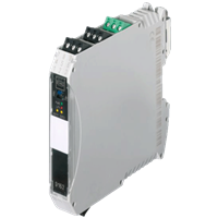
Transmitter Supply Unit with Limit Value Series 9162 - Non Ex i
Brand: R. STAHL AG9162 series transmitter power supply units with limit values can be used for the operation of two- and three-conductor transmitters or for connecting to mA sources.
Two limit values can be easily set using the ISpac Wizard software.
If the value exceeds or falls below these limit values, these units will issue an alert.
A wire-breakage and short-circuit monitoring system affords increased availability.
Features- Compact limit value switch with two configurable limit values and output of 4 to 20 mA
- bidirectional HART transmission
- can be used up to SIL 2 (IEC/EN 61508)
1 - 2 of 2 Part Numbers
238253
Compact limit value switch with two configurable limit values and output of 4 to 20 mA
bidirectional HART transmission
can be used up to SIL 2 (IEC/EN 61508)
Ambient Conditions
- Ambient temperature - -40 °C ... +70 °C (Single device) -40 °C ... +60 °C (Group assembly)
- Ambient temperature max. - +70 °C
- Ambient temperature max. note - Single device
- Ambient temperature max. note 2 - Group assembly
- Ambient temperature max.2 - +60 °C
- Ambient temperature min. - -40 °C
- Ambient temperature min. 2 - -40 °C
- Ambient temperature min. note - Single device
- Ambient temperature min. note 2 - Group assembly
- Electromagnetic compatibility - Tested to the following standards and regulations: EN 61326-1 Use in industrial environment
- Relative humidity max. - 95%
- Storage temperature - -40 °C ... +80 °C
- Storage temperature max. - +80 °C
- Storage temperature min. - -40 °C
- Use at the height of - < 2000 m
Auxiliary power
- Auxiliary power - 24 V DC
- Auxiliary power nom. voltage - 24 V DC
- Auxiliary power voltage range - 18 ... 31,2 V
- Nominal current - 85.00 mA
- Operation indication - Green "PWR" LED
- Polarity reversal protection - yes
- Power consumption - 2.00 W
- Power dissipation max. - 1.50 W
- Undervoltage monitoring - Yes
- Voltage range residual ripple - ≤ 3,6 VSS
Electrical Data
- communication signal - HART, 0.5 .... 10 kHz
- Isolating repeater mode - Yes
- Limiting values configuration - using ISpac wizard (V3.04.00 and following)
- Number of channels - 1
- Transmitter supply mode - Yes
Explosion Protection
- Application range (zones) - 2, 22
- ATEX gas certificate - BVS 15 ATEX E017 X
- Certificate EAC - TS RU S-DE.GB04.B.00353
- Certificates - ATEX (BVS), Canada (FM), EAC (STV), IECEx (BVS), India (PESO), SIL (exida), USA (FM)
- Ex interface zone - 20, 21, 22
- Gas explosion protection ATEX - II 3 G Ex nA nC IIC T4 Gc
- Gas explosion protection EAC - 2 Ex nA nC II T4 Gc X
- Gas explosion protection IECEx - Ex nA nC IIC T4 Gc
- IECEX gas certificate - IECEx BVS 15.0013 X
- Ship approval - CCS, DNVGL
Galvanic isolation
- Galvanic isolation Ex i input to auxiliary power - 1.5 kV AC
- Galvanic isolation Ex i input to fault message contact - 1,5 kV AC
- Galvanic isolation Ex i input to output - 1.5 kV AC
- Galvanic isolation fault message contact to power supply - 350 V AC
- Galvanic isolation output to auxiliary power - 350 V AC
- Galvanic isolation output to output - 350 V AC
- Test voltage according to standard - IEC EN 60079-11
- Test voltage according to standard 2 - EN 50178
General
- Functional Description - 9162 series transmitter power supply units with limit values can be used for the operation of two- and three-conductor transmitters or for connecting to mA sources. Two limit values can be easily set using the ISpac Wizard software. If the value exceeds or falls below these limit values, these units will issue an alert. A wire-breakage and short-circuit monitoring system affords increased availability.
- Highlights - Compact limit value switch with two configurable limit values and output of 4 to 20 mA bidirectional HART transmission can be used up to SIL 2 (IEC/EN 61508)
- Product Description - Transmitter supply unit With limit contact Non-Ex i field circuit
- Product Type - 9162/13-11-64s
- Product Variant - Transmitter supply unit with limit contact
- Title Product Variant Technical Data - 9162/13-11-64s transmitter supply u.w.G
- WebCode - 9162B
Input
- Input - 4 ... 20 mA with HART
- Input current max. mA sources - 50 mA
- Input function - Isolation amplifier Transmitter power unit
- Input functional range - 2 - 22 mA
- Input open circuit voltage U a - ≤ 26 V
- Input resistance - 30 ohms
- input signal - 4 ... 20 mA with HART
- Message of line fault and Auxilliary power failure - - Contact (30 V / 100 mA) closed to ground in case of fault - pac-Bus, floating contact (30 V / 100 mA)
- short-circuit current - ≤ 35 mA
- Supply voltage for transmitter - ≥ 16 V at 20 mA
- Supply voltage note - (T < -10 °C: US - 0.2 V / 10K)
Mechanical Data
- Connection cross-section - 0.2-2.5 mm² flexible 0.25-2.5 mm² flexible core end sleeve
- Degree of protection (IP) - IP30
- Enclosure material - Polyamide
- Fire resistance (UL 94) - V0
- Grid dimension - 17.60 mm
- Terminal degree of protection (IP) - IP20
- Weight - 0.225 kg
Mounting / Installation
- Conduct cross-section flexible max. - 0.2 mm²
- Conduct cross-section flexible max. - 2.5 mm²
- Conductor cross-section solid max. - 2.5 mm²
- Conductor cross-section solid min. - 0.2 mm²
- Connection type - Screw terminal
- Mounting position - horizontal vertical
- Mounting type - NS35/15, NS35/7.5 DIN rail
Output
- Analog signal delay - < 30 ms
- Auxiliary power influence error limits - ≤ 0,01 %
- Behaviour of the output - = input signal
- deviation - ≤ 0,2 %
- Error detection wire breakage - < 3.6 mA
- Indication of line fault - "LF" LED, red
- LFD relay - Yes
- Limit contact (per channel) - 2 NOs
- linearity error - ≤ 0,1 %
- Load resistance influence - ≤ 0,02 %
- Load resistance R L - 0 … 600 Ω (terminal 1+ / 2-)
- Load resistance R L max. - 600.00 Ω
- offset error - ≤ 0,1 %
- Output - 4 ... 20 mA with HART
- Output A - 2 ... 22 mA
- Output functional range - 2.0 - 22.0 mA
- Output residual ripple - ≤ 40 µAeff
- output signal - 4 ... 20 mA with HART
- Settling time 10 … 90 % - < 45 ms
- Short circuit error detection - > 21 mA
- Switch user adjustment line fault - activated / deactivated
- Switch-back delay - < 100 ms
- Switch-on resistance - ≤ 2.5 ohms (typical < 1 ohm)
- Switching capacity fault message contact - 30 V / 100 mA
- Switching current limiting values - ≤ 100 mA
- switching delay - < 80 ms
- Switching state indication - Yellow LED "OUT"
- Switching voltage limiting values - ≤ ± 30 V
- Temperature influence error limits - ≤ 0.1% / 10 K
Safety Data
- Internal capacitance C i - negligible
- Internal inductance L i - negligible
238277
Compact limit value switch with two configurable limit values and output of 4 to 20 mA
bidirectional HART transmission
can be used up to SIL 2 (IEC/EN 61508)
Ambient Conditions
- Ambient temperature - -40 °C ... +70 °C (Single device) -40 °C ... +60 °C (Group assembly)
- Ambient temperature max. - +70 °C
- Ambient temperature max. note - Single device
- Ambient temperature max. note 2 - Group assembly
- Ambient temperature max.2 - +60 °C
- Ambient temperature min. - -40 °C
- Ambient temperature min. 2 - -40 °C
- Ambient temperature min. note - Single device
- Ambient temperature min. note 2 - Group assembly
- Electromagnetic compatibility - Tested to the following standards and regulations: EN 61326-1 Use in industrial environment
- Relative humidity max. - 95%
- Storage temperature - -40 °C ... +80 °C
- Storage temperature max. - +80 °C
- Storage temperature min. - -40 °C
- Use at the height of - < 2000 m
Auxiliary power
- Auxiliary power - 24 V DC
- Auxiliary power nom. voltage - 24 V DC
- Auxiliary power voltage range - 18 ... 31,2 V
- Nominal current - 85.00 mA
- Operation indication - Green "PWR" LED
- Polarity reversal protection - yes
- Power consumption - 2.00 W
- Power dissipation max. - 1.50 W
- Undervoltage monitoring - Yes
- Voltage range residual ripple - ≤ 3,6 VSS
Electrical Data
- communication signal - HART, 0.5 .... 10 kHz
- Isolating repeater mode - Yes
- Limiting values configuration - using ISpac wizard (V3.04.00 and following)
- Number of channels - 1
- Transmitter supply mode - Yes
Explosion Protection
- Application range (zones) - 22
- ATEX gas certificate - BVS 15 ATEX E017 X
- Certificate EAC - TS RU S-DE.GB04.B.00353
- Certificates - ATEX (BVS), Canada (FM), EAC (STV), IECEx (BVS), India (PESO), SIL (exida), USA (FM)
- Ex interface zone - 0, 1, 2, 20, 21, 22
- Gas explosion protection ATEX - II 3 G Ex nA nC IIC T4 Gc
- Gas explosion protection EAC - 2 Ex nA nC IIC T4 Gc X
- Gas explosion protection IECEx - Ex nA nC IIC T4 Gc
- IECEX gas certificate - IECEx BVS 15.0013 X
- Ship approval - CCS, DNVGL
Galvanic isolation
- Galvanic isolation Ex i input to auxiliary power - 1.5 kV AC
- Galvanic isolation Ex i input to fault message contact - 1,5 kV AC
- Galvanic isolation Ex i input to output - 1.5 kV AC
- Galvanic isolation fault message contact to power supply - 350 V AC
- Galvanic isolation output to auxiliary power - 350 V AC
- Galvanic isolation output to output - 350 V AC
- Test voltage according to standard - IEC EN 60079-11
- Test voltage according to standard 2 - EN 50178
General
- Functional Description - 9162 series transmitter power supply units with limit values can be used for the operation of two- and three-conductor transmitters or for connecting to mA sources. Two limit values can be easily set using the ISpac Wizard software. If the value exceeds or falls below these limit values, these units will issue an alert. A wire-breakage and short-circuit monitoring system affords increased availability.
- Highlights - Compact limit value switch with two configurable limit values and output of 4 to 20 mA bidirectional HART transmission can be used up to SIL 2 (IEC/EN 61508)
- Product Description - Transmitter supply unit With limit contact Non-Ex i field circuit
- Product Type - 9162/13-11-64k
- Title Product Variant Technical Data - 9162/13-11-64k transmitter supply u.w.G
- WebCode - 9162B
Input
- Input - 4 ... 20 mA with HART
- Input current max. mA sources - 50 mA
- Input function - Isolation amplifier Transmitter power unit
- Input functional range - 2 - 22 mA
- Input open circuit voltage U a - ≤ 26 V
- Input resistance - 30 ohms
- input signal - 4 ... 20 mA with HART
- Message of line fault and Auxilliary power failure - - Contact (30 V / 100 mA) closed to ground in case of fault - pac-Bus, floating contact (30 V / 100 mA)
- short-circuit current - ≤ 35 mA
- Supply voltage for transmitter - ≥ 16 V at 20 mA
- Supply voltage note - (T < -10 °C: US - 0.2 V / 10K)
Mechanical Data
- Degree of protection (IP) - IP30
- Enclosure material - Polyamide
- Fire resistance (UL 94) - V0
- Grid dimension - 17.60 mm
- Terminal degree of protection (IP) - IP20
- Weight - 0.225 kg
Mounting / Installation
- Conduct cross-section flexible max. - 0.2 mm²
- Conduct cross-section flexible max. - 2.5 mm²
- Conductor cross-section solid max. - 2.5 mm²
- Conductor cross-section solid min. - 0.2 mm²
- Connection type - Spring clamp terminal
- Mounting position - horizontal vertical
- Mounting type - NS35/15, NS35/7.5 DIN rail
Output
- Analog signal delay - < 30 ms
- Auxiliary power influence error limits - ≤ 0,01 %
- Behaviour of the output - = input signal
- deviation - ≤ 0,2 %
- Error detection wire breakage - < 3.6 mA
- Indication of line fault - "LF" LED, red
- LFD relay - Yes
- Limit contact (per channel) - 2 NOs
- linearity error - ≤ 0,1 %
- Load resistance influence - ≤ 0,02 %
- Load resistance R L - 0 … 600 Ω (terminal 1+ / 2-)
- Load resistance R L max. - 600.00 Ω
- offset error - ≤ 0,1 %
- Output - 4 ... 20 mA with HART
- Output A - 2 ... 22 mA
- Output functional range - 2.0 - 22.0 mA
- Output residual ripple - ≤ 40 µAeff
- output signal - 4 ... 20 mA with HART
- Settling time 10 … 90 % - < 45 ms
- Short circuit error detection - > 21 mA
- Switch user adjustment line fault - activated / deactivated
- Switch-back delay - < 100 ms
- Switch-on resistance - ≤ 2.5 ohms (typical < 1 ohm)
- Switching capacity fault message contact - 30 V / 100 mA
- Switching current limiting values - ≤ 100 mA
- switching delay - < 80 ms
- Switching state indication - Yellow LED "OUT"
- Switching voltage limiting values - ≤ ± 30 V
- Temperature influence error limits - ≤ 0.1% / 10 K
Safety Data
- Internal capacitance C i - negligible
- Internal inductance L i - negligible
1 - 2 of 2 Part Numbers