

Yodify Product Library
Add the Binary Output Series 9275 to your store or catalog
Book Your Demo and See How
or create your store

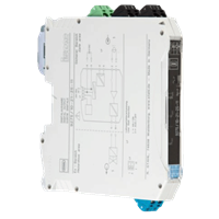
Binary Output Series 9275
Brand: R. STAHL AGSeries 9275 digital outputs issue signals for the intrinsically safe operation of Ex i solenoid valves, indicator lamps or horns. The devices feature three-way galvanic separation.
Features- Space savings due to a slim design – 12.5 mm wide
- Can be used for functional safety levels up to SIL 3 (IEC/EN 61508)
- Offers line fault detection with signalization
1 - 2 of 2 Part Numbers
261434
Space savings due to a slim design – 12.5 mm wide
Can be used for functional safety levels up to SIL 3 (IEC/EN 61508)
Offers line fault detection with signalization
Ambient Conditions
- Ambient temperature - -20 °C ... +60 °C
- Ambient temperature max. - +60 °C
- Ambient temperature min. - -20 °C
- Electromagnetic compatibility - EN 61326-1 Use in industrial environment Immunity according to EN 61000-6-2 Interference emission to EN 61000-6-4
- Relative humidity max. - 10 to 95%
- Storage temperature - -40 °C ... +80 °C
- Storage temperature max. - +80 °C
- Storage temperature min. - -40 °C
- Use at the height of - < 2000 m
Auxiliary power
- Auxiliary power - 24 V DC
- Auxiliary power voltage range - 19,2 … 30 V
- Nominal current - 50.00 mA
- Operation indication - Green "PWR" LED
- Polarity reversal protection - yes
- Power consumption - 1.20 W
- Power dissipation max. - 0.80 W
- Undervoltage monitoring - No
Electrical Data
- Number of channels - 1
Explosion Protection
- Application range (zones) - 2, 22
- ATEX dust certificate - IBExU 17 ATEX 1152 X
- ATEX gas certificate - IBExU 17 ATEX 1152 X
- Certificates - ATEX (IBE), Canada / USA (UL), IECEx (IBE), SIL (BVS)
- Dust explosion protection ATEX - II (1) D [Ex ia Da] IIIC
- Dust explosion protection IECEx - [Ex ia Da] IIIC
- Ex interface in Division NEC 500 - (Class I, II, III) 1, 2
- Ex interface zone - 0, 1, 2, 20, 21, 22
- Gas explosion protection ATEX - II 3 (1) G Ex nA [ia Ga] IIC T4 Gc
- Gas explosion protection IECEx - Ex nA [ia Ga] IIC T4 Gc
- IECEX dust certificate - IECEx IBE 17.0044X
- IECEX gas certificate - IECEx IBE 17.0044X
- Installation in Division NEC 500 - (Class I, II, III) 2
Galvanic isolation
- Galvanic isolation Ex i output to auxiliary power - 375 V AC peak value
- Galvanic isolation Ex i output to fault message contact - 375 V AC peak value
- Galvanic isolation Ex i output to input - 375 V AC peak value
- Galvanic isolation fault message contact to auxiliary power - 300 Veff
- Galvanic isolation fault message contact to input - 300 Veff
- Galvanic isolation input to auxiliary power - 300 Veff
- Test voltage according to standard - IEC EN 60079-11
- Test voltage according to standard 2 - EN 61010 / EN 50178
General
- Functional Description - Series 9275 digital outputs issue signals for the intrinsically safe operation of Ex i solenoid valves, indicator lamps or horns. The devices feature three-way galvanic separation.
- Highlights - Space savings due to a slim design – 12.5 mm wide Can be used for functional safety levels up to SIL 3 (IEC/EN 61508) Offers line fault detection with signalization
- Product Description - Binary output Ex i field circuit
- Product Type - 9275/10-21-25-11s
- Title Product Variant Technical Data - 9275/10-21-25-11s
- WebCode - 9275A
Input
- Control current - < 12 mA
- Input voltage for OFF - 0 - 5 V
- Input voltage for ON - 15.0 - 30.0 V
Mechanical Data
- Connection cross-section - 0.2-2.5 mm² rigid 0.25-2.5 mm² flexible core end sleeve
- Degree of protection (IP) - IP30
- Enclosure material - Polyamide
- Fire resistance (UL 94) - V0
- Grid dimension - 12.50 mm
- Terminal degree of protection (IP) - IP20
- Weight - 0.160 kg
Mounting / Installation
- Conduct cross-section flexible max. - 2.5 mm²
- Conduct cross-section flexible max. - 0.2 mm²
- Conductor cross-section solid max. - 2.5 mm²
- Conductor cross-section solid min. - 0.2 mm²
- Connection type - Screw terminal
- Mounting position - vertical horizontal
- Mounting type - NS35/15, NS35/7.5 DIN rail
Output
- Error detection wire breakage - > 10 kΩ
- Indication of line fault - "LF" LED, red
- LFD relay - Yes
- Max. output current I a max - 25.10 mA
- Output internal resistiance R i - 641.00 Ω
- Output open circuit voltage U a - 21,1 V
- Response time output - < 30 ms
- Short circuit error detection - < 50 Ω
- Switch user adjustment line fault - activated / deactivated
- Switching capacity fault message contact - 30 V / 50 mA
- Switching delay ON/OFF - < 30 ms
- Switching state indication - Yellow LED "STAT"
- test current - < 0.6 mA
Safety Data
- Internal capacitance C i - 11 nF
- Internal inductance L i - negligible
- Max. current I o (Ex ia) - 37.40 mA
- Max. permissible external capacitance C o for IIA - 3.330 μF
- Max. permissible external capacitance C o for IIB - 0.910 μF
- Max. permissible external capacitance C o for IIC - 0.110 μF
- Max. permissible external inductance L o for IIA - 200.00 mH
- Max. permissible external inductance L o for IIB - 100.000 mH
- Max. permissible external inductance L o for IIC - 22.000 mH
- Max. Power P o - 224.000 mW
- Max. Voltage U o - 23.98 V
- Safety-related maximum voltage - 253 V AC
261435
Space savings due to a slim design – 12.5 mm wide
Can be used for functional safety levels up to SIL 3 (IEC/EN 61508)
Offers line fault detection with signalization
Ambient Conditions
- Ambient temperature - -20 °C ... +60 °C
- Ambient temperature max. - +60 °C
- Ambient temperature min. - -20 °C
- Electromagnetic compatibility - EN 61326-1 Use in industrial environment Immunity according to EN 61000-6-2 Interference emission to EN 61000-6-4
- Relative humidity max. - 10 to 95%
- Storage temperature - -40 °C ... +80 °C
- Storage temperature max. - +80 °C
- Storage temperature min. - -40 °C
- Use at the height of - < 2000 m
Auxiliary power
- Auxiliary power - 24 V DC
- Auxiliary power voltage range - 19,2 … 30 V
- Nominal current - 90.00 mA
- Operation indication - Green "PWR" LED
- Polarity reversal protection - yes
- Power consumption - 2.16 W
- Power dissipation max. - 1.62 W
- Undervoltage monitoring - No
Electrical Data
- Number of channels - 1
Explosion Protection
- Application range (zones) - 2, 22
- ATEX dust certificate - IBExU 17 ATEX 1152 X
- ATEX gas certificate - IBExU 17 ATEX 1152 X
- Certificates - ATEX (IBE), Canada / USA (UL), IECEx (IBE), SIL (BVS)
- Dust explosion protection ATEX - II (1) D [Ex ia Da] IIIC
- Dust explosion protection IECEx - [Ex ia Da] IIIC
- Ex interface in Division NEC 500 - (Class I, II, III) 1, 2
- Ex interface zone - 0, 1, 2, 20, 21, 22
- Gas explosion protection ATEX - II 3 (1) G Ex nA [ia Ga] IIC T4 Gc
- Gas explosion protection IECEx - Ex nA [ia Ga] IIC T4 Gc
- IECEX dust certificate - IECEx IBE 17.0044X
- IECEX gas certificate - IECEx IBE 17.0044X
- Installation in Division NEC 500 - (Class I, II, III) 2
Galvanic isolation
- Galvanic isolation Ex i output to auxiliary power - 375 V AC peak value
- Galvanic isolation Ex i output to fault message contact - 375 V AC peak value
- Galvanic isolation Ex i output to input - 375 V AC peak value
- Galvanic isolation fault message contact to auxiliary power - 300 Veff
- Galvanic isolation fault message contact to input - 300 Veff
- Galvanic isolation input to auxiliary power - 300 Veff
- Test voltage according to standard - IEC EN 60079-11
- Test voltage according to standard 2 - EN 61010 / EN 50178
General
- Functional Description - Series 9275 digital outputs issue signals for the intrinsically safe operation of Ex i solenoid valves, indicator lamps or horns. The devices feature three-way galvanic separation.
- Highlights - Space savings due to a slim design – 12.5 mm wide Can be used for functional safety levels up to SIL 3 (IEC/EN 61508) Offers line fault detection with signalization
- Product Description - Binary output Ex i field circuit
- Product Type - 9275/10-24-48-11s
- Title Product Variant Technical Data - 9275/10-24-48-11s
- WebCode - 9275A
Input
- Control current - < 12 mA
- Input voltage for OFF - 0 - 5 V
- Input voltage for ON - 15.0 - 30.0 V
Mechanical Data
- Degree of protection (IP) - IP30
- Enclosure material - Polyamide
- Fire resistance (UL 94) - V0
- Grid dimension - 12.50 mm
- Terminal degree of protection (IP) - IP20
- Weight - 0.160 kg
Mounting / Installation
- Conduct cross-section flexible max. - 2.5 mm²
- Conduct cross-section flexible max. - 0.2 mm²
- Conductor cross-section solid max. - 2.5 mm²
- Conductor cross-section solid min. - 0.2 mm²
- Connection type - Screw terminal
- Mounting position - vertical horizontal
- Mounting type - NS35/15, NS35/7.5 DIN rail
Output
- Error detection wire breakage - > 10 kΩ
- Indication of line fault - "LF" LED, red
- LFD relay - Yes
- Max. output current I a max - 48.00 mA
- Output internal resistiance R i - 297.00 Ω
- Output open circuit voltage U a - 24,3 V
- Response time output - < 30 ms
- Short circuit error detection - < 50 Ω
- Switch user adjustment line fault - activated / deactivated
- Switching capacity fault message contact - 30 V / 50 mA
- Switching delay ON/OFF - < 30 ms
- Switching state indication - Yellow LED "STAT"
- test current - < 0.6 mA
Safety Data
- Internal capacitance C i - 11 nF
- Internal inductance L i - negligible
- Max. current I o (Ex ia) - 91.11 mA
- Max. permissible external capacitance C o for IIA - 2.290 μF
- Max. permissible external capacitance C o for IIB - 0.686 μF
- Max. permissible external capacitance C o for IIC - 0.078 μF
- Max. permissible external inductance L o for IIA - 32.00 mH
- Max. permissible external inductance L o for IIB - 15.000 mH
- Max. permissible external inductance L o for IIC - 3.500 mH
- Max. Power P o - 616.000 mW
- Max. Voltage U o - 27.06 V
- Safety-related maximum voltage - 253 V AC
1 - 2 of 2 Part Numbers