

Yodify Product Library
Add the Analog Universal Module HART for Zone 2 Series 9468/33 to your store or catalog
Book Your Demo and See How
or create your store

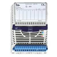
Analog Universal Module HART for Zone 2 Series 9468/33
Brand: R. STAHL AGThe 9468/33 series HART Analog Universal Module for Zone 2 has eight channels that can be used individually for Ex i operating two-/three-conductor HART transmitters, four-conductor transmitters or control valves/positioners with 0/4 to 20 mA signals.
HART communication is bidirectional. All inputs/outputs are short-circuit proof, galvanically separated from the system and individually monitored to check for line faults.
Features- Eight channels can be used individually as inputs or outputs
- intrinsically safe Ex ia IIC inputs/outputs with line fault monitoring
- module in Zone 2 can be hot swapped
1 - 1 of 1 Part Numbers
210660
Eight channels can be used individually as inputs or outputs
intrinsically safe Ex ia IIC inputs/outputs with line fault monitoring
module in Zone 2 can be hot swapped
Ambient Conditions
- Ambient temperature - -40 °C ... +75 °C
- Ambient temperature max. - +75 °C
- Ambient temperature min. - -40 °C
- Ambient temperature note - observe operating instructions
- Electromagnetic compatibility - Tested to the following standards and regulations: EN 61326-1 (2006) IEC 61000-4-1 to 61000-4-6, NAMUR NE 21
- Max. operating height - < 2000 m
- Max. relative humidity - 95% (without condensation)
- Shock (semi-sinusoidal) - (IEC EN 60068-2-27) 15 g (3 shocks per axis and direction)
- Storage temperature - -40 °C ... +80 °C
- Storage temperature max. - +80 °C
- Storage temperature min. - -40 °C
- Vibration (sinusoidal) - (IEC EN 60068-2-6) 1 g in the frequency range 10 … 500 Hz 2 g in the frequency range 45 … 100 Hz
Auxiliary power
- Auxiliary power Version - Intrin. safe Ex ia via BusRail
- Current consumption - 220 mA (at 20 mA per channel)
- Max. power consumption - 5.30 W (at 20 mA / channel)
- Max. power dissipation inputs - 2.7 W (at 20 mA / channel)
- max. power dissipation inputs note - (at 20 mA / channel)
- Max. power dissipation of outputs - 3.7 W
- max. power dissipation output note - (at 20 mA, 500 Ohm / channel)
- Max. power dissipation outputs - 3.7 W (at 20 mA, 500 Ohm / channel)
- Power consumption max. - 5.30 W
- Power consumption Note - (at 20 mA / channel)
- Power supply connection - BusRail types 9494
Device Specific Data
- Cyclic transmis. of HART var. - no 8HV 4HV
- In. behaviour in case of error - 110% 100% 0% -10% Alarm code, keep last value
- Infl. of ambient temperature - < 0,03 % / 10 K
- Input measuring range - 3.6 ... 21 mA (acc. to NAMUR) 2.4 ... 22.8 or 23.5 mA
- LED group error - "ERR" LED, red
- LED operating state - "RUN" LED, green
- LEDmodule requires maintenance - "M/S" LED, blue
- Line fault monitoring - OFF ON
- Module diagnostics message - ON OFF
- Module scan HART live list - ON OFF
- Module signal filter - 50 Hz large 60 Hz large medium small
- Module status and alarms - Internal bus error primer / redundant No response from IOM Configuration does not correspond to the module Hardware error Excess temperature Slot error Module requires maintenance
- Out. behav. in case of error - -10% 0% 100% 110% Keep last value
- Retrievable parameters - type software revision serial number manufacturer hardware revision
- Short circuit input - > 23,5 mA > 22,8 mA / > 21 mA (adjustable parameters)
- Short circuit output - Output load < 60 Ω (response range 40 ... 60 Ω )
- Signal range - 0 ... 20 mA 4 ... 20 mA
- Signal status bit - 1 = Signal valid 0 = Signal interrupted
- Wire breakage input - < 2,4 mA / 3,6 mA (adjust. param., at 4 ... 20)
- Wire breakage output - Terminal voltage > 16 V (response range 16 ... 16.5 V) or output current can not longer be set
Electrical Data
- Channels - each with adjustable parameters as input or output (3-wire, 4-wire transmitters, or active mA-sources occupy 2 channels)
- communication signal - HART protocol
- Connection Ex i field signals - Pluggable, blue terminals, 16-pole, 2.5 mm 2 , screw- or spring-type versions with lock
- Nominal signal - 4 ... 20 mA 0 ... 20 mA
- Notes - In order to operate an active 4-wire HART transmitter, a 9164 must be connected between each channel. 9164 is not required when operating 4-wire transmitter without HART communication.
- Number of channels - 8 Ex i inputs/outputs
- Supply voltage - 16.00 V, at 20 mA for 2-wire transmitters
- Supply voltage, 2-conductor - 16.00 V
Explosion Protection
- Ambient temperature °C - -40 - 75 °C
- Application range (Zone) Note - A suitable enclosure in accordance with the area of application must be used. Refer to the operating instructions.
- Application range (zones) - 2, 22
- ATEX dust certificate - DEKRA 12 ATEX0173 X
- ATEX gas certificate - DEKRA 12 ATEX0173 X
- Certificate EAC - TS RU S-DE.GB04.B.00448
- Certificates - ATEX (DEK), Brazil (ULB), Canada (FM), EAC (STV), IECEx (DEK), India (PESO), Korea (KTL), Russia (Meteorological certificate), USA (FM)
- Dust explosion protection ATEX - II (1) D [Ex ia Da] IIIC
- Dust explosion protection EAC - [Ex ia Da] IIIC
- Dust explosion protection IECEx - [Ex ia Da] IIIC
- Ex interface zone - 0, 1, 2, 20, 21, 22
- Further information - see operating instructions and certificate
- Gas explosion protection ATEX - II 3 (1) G Ex nA ia [ia Ga] IIC T4 Gc
- Gas explosion protection EAC - 2 Ex nA ia [ia Ga] IIC T4 Gc X
- Gas explosion protection IECEx - Ex nA ia [ia Ga] IIC T4 Gc
- IECEX dust certificate - IECEx DEK 12.0054X
- IECEX gas certificate - IECEx DEK 12.0054X
- Installation - Zone 2, Zone 21, Zone 22 and in the safe area
- Ship approval - ABS, CCS, ClassNK, DNVGL, RINA
Galvanic isolation
- Aux. power/system components - ≥ 1500 V AC
- I/O channels / ground (PA) - ≥ 500 V AC
- I/O channels/system components - ≥ 500 V AC
- I/O module / I/O module - ≥ 500 V AC
- Test volt. for gal. separation - acc. to standard EN 60079-11
General
- Functional Description - The 9468/33 series HART Analog Universal Module for Zone 2 has eight channels that can be used individually for Ex i operating two-/three-conductor HART transmitters, four-conductor transmitters or control valves/positioners with 0/4 to 20 mA signals. HART communication is bidirectional. All inputs/outputs are short-circuit proof, galvanically separated from the system and individually monitored to check for line faults.
- Highlights - Eight channels can be used individually as inputs or outputs intrinsically safe Ex ia IIC inputs/outputs with line fault monitoring module in Zone 2 can be hot swapped
- Product Description - Remote I/O IS1+ HART analog universal module for Zone 2 Ex i
- Product Type - 9468/33-08-10
- Title Product Variant Technical Data - 9468/33-08-10 AUMH 08 Z2
- WebCode - 9468B
Input
- Max. input resistance - 14.1 ohms per channel
- Max. short-circuit current in. - 24 mA
- Max. signal for input - 23.5 mA
- Signal type - output input
Mechanical Data
- Degree of protection IP (IEC 60529) - IP20
- Fire resistance (UL 94) - V2
- Module enclosure - Polyamide 6GF
- Pollutant class - Corresponds to G3
- Weight - 0.275 kg
Mounting / Installation
- Mounting position - horizontal vertical
- Mounting type - on DIN rail NS 35/15
- Mounting type 2 - (DIN EN 60715)
Output
- Max. output short-cir. curr. - 22,8 mA (4 ... 20 mA) 23,5 mA (0 ... 20 mA)
- Max. signal for output - 22,8 mA (4 ... 20 mA), 22,8 mA (4 ... 20 mA) 23,5 mA (0 ... 20 mA)
- Output load resistance max. - 750 ohms at 20 mA 700 ohms at 21.8 mA
- Output step response (10 … 90 %) - 40 Millisecond
Safety Data
- Internal capacitance C i - negligible
- Internal inductance L i - negligible
- Max. current I o (2-conductor) - 80.0 mA
- Max. current I o (3-conductor) - 81.8 mA
- Max. power P o (2-conductor) - 488.0 mW
- Max. power P o (3-conductor) - 499.0 mW
- Max. Voltage U o - 24.40 V
1 - 1 of 1 Part Numbers