Yodify Product Library
Add the PHA Inkjet Strip Chart Recorder to your store or catalog
Book Your Demo and See How
or create your store
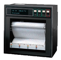
PHA Inkjet Strip Chart Recorder
Brand: Fuji Electric Co, LtdThis recorder can record a maximum of 12 channels of DC voltage, mA, thermocouples and resistance bulbs.
The adoption of an ink jet system makes it possible to record measured data in Analog trace mode or to print in digital mode at a high speed.
This 180 mm-wide recorder performs recording clearly in 6 different colors.
Features- Compact size
- High quality recording
- Easy setting of input signals
- Digital printing
- Interactive key operation
- Easy handling
- Full variety of functions
Specifications
Brand
Accuracy
- Chart Speed Accuracy: ± 0.1 % (Expansion & Contraction of Paper is Not Included)
- Clock Accuracy: ± 50 ppm or Less (Monthly Error, About 2 minutes)
- Reference Junction Compensation (K, E, J, T, N, L, U, PN Thermocouple): ± 0.5° C (± 0.9° F)
- Reference Junction Compensation (R, S, B, W Thermocouple): ± 1° C (± 1.8° F)
- Thermocouple, Resistance Bulb, DC Voltage: ± (0.15 % + 1-Digit)
- Thermocouple, RTD, DC Voltage: ± 0.25 % of Recording Span
Communication
- Transmission Method: Half-Duplex Bit Serial, 500 Kbps Up to, Max.
Consumption
- 100 Vac & 24 Vdc with All Options Approximately: 37 VA
- 240 Vac with All Options Approximately: 56 VA
Electrical Contacts
- Normally Open
Electrical Rating
- 3 A at 240 Vac / 30 Vdc
- Contact Capacity: 0.05 A at 12 Vdc, Normally Open
Enclosure, Body Material
- Steel Plate
Environmental Protection
- Front: IEC IP50
- Terminal: IP20
Function
- Alarm
- Recording Switch on Camera
Humidity
- Chart Paper Influence (Contraction): 35 % RH, 0.5 %, max.
- Chart Paper Influence (Expansion): 85 % RH, 0.4 %, max.
- Operating Environment: 20 to 80 % RH, Non-Condensing
- Transportation/Storage Condition: 5 to 90 % RH, Non-Condensing
Hysteresis
- 0.5 % of Recording Span
Indication
- Status Display Icon
Input
- DC Voltage Input (5 V, 50 V Range): -100 to 100 Vdc or Less
- Thermocouple, Resistance Bulb & DC Voltage (50 mV, 500 mV Range): -10 Vdc or Less
Input Signal
- -50 to 50 V
- -500 to 500 mV
Insulation Resistance
- 100 MΩ or more (Between each Terminal & Earth, at 500 Vdc)
Materials of Construction
- Front Door Frame: Polycarbonate with Glass Wool
Mounting
- Inclined up to 30° Backwards from the Vertical: Panel
Mounting Position
- Front & Left/Right Inclination: 0°
- Rear Inclination: 30°
Mounting Position Effect
- Change in Indication: ± (0.1 % + 1-Digit) - Max.
- Changing in Recording: ± 0.2 % of Recording Span, Max.
Operating Temperature
- 0° to 50° C (32° to 122° F)
Output Noise
- Common Mode Noise Rejection: 120 dB at 50, 60 Hz ± 0.1 Hz
- Series Mode Noise Rejection: 30 dB at 50, 60 Hz ± 0.1 Hz
Power Supply
- 100-240 Vac (10 %, ± 15 %), 50/60 Hz
- 24 Vdc, ± 10 %
Power Supply Effect
- Change in Indication: ± (0.1 % + 1-Digit) - Max.
- Change in Recording: ± 0.2 % of Recording Span, Max.
Resistance
- Input (5 V & 50 V): ≥ 1 MΩ
- Input (Thermocouple & 50 mV): > 10 MΩ
- Iput (500 mV): > 100 kΩ
- Signal Source Resistance (Resistance Bulb Input): less than 10 ohms Per Line
- Signal Source Resistance (Thermocouple Input): 1 Kiloohm or Less Voltage
Resistance Effect
- Change in Indication (Thermocouple & RTD): ± (0.1 % + 1-Digit)
- Change in Recording (Thermocouple & RTD): ± 0.2 % of Span
- Voltage Input: 0.1 % Change of Resistance
Resolution
- DC Voltage: 10 µA to 10 mA
- Thermocouple, Resistance Bulb: 0.1° C
- Thermocouple, RTD, DC Voltage: 0.1 mm Min.
RTD Type
- Pt100 as Per IEN 60751
Sensor, Probe Type
- B Thermocouple as Per EN 60584
- C Thermocouple
- D Thermocouple
- E Thermocouple
- J Thermocouple
- K Thermocouple
- L Thermocouple as Per DIN 43710
- N Thermocouple
- PN Thermocouple
- RTD
- R Thermocouple
- S Thermocouple
- T Thermocouple
- U Thermocouple as Per DIN 43710
Shock
- 294 m/sec² (30 G) or Less
Storage Temperature
- -10° to 60° C (14° to 140° F)
Supply Voltage
- Withstand Voltage: between Alarm Terminals 750 Vac for 1 Minute
- Withstand Voltage: Input Terminal - Input Terminal, Input Terminal - Ground, Power Terminal - Input Terminal 500 Vac for 1 Minute
- Withstand Voltage: Power Supply Terminal - Ground 2,000 Vac for 1 Minute
Temperature Effect
- Change in Indication: ± (0.3 % + 1-Digit)/10° C (18° F) - Max.
- Change in Recording: ± 0.5 %/10° C (18° F) - Max.
Temperature Range
- RTD: -200° to 600° C (-328° to 1,112° F)
- Thermocouple: -200° to 1,760° C (-328° to 3,200° F)
Terminal Strip
- External Terminals: Screw Terminal Strip (M4 Screws)
Update Time
- Warm-Up Time: 30 minutes or more
Vibration
- Operating Environment: 10-60 Hz, 0.2 m/sec² (0.02 G) or Less
- Transportation/Storage Condition: 2.45 m/sec² (3 G) or Less
Vibration Effect
- Change in Indication: ± (0.1 % + 1-Digit) - Max.
- Change in Recording: ± 0.2 % of Recording Span, Max.


