

Yodify Product Library
Add the Transmitter Supply Unit Series 9160 to your store or catalog
Book Your Demo and See How
or create your store

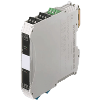
Transmitter Supply Unit Series 9160
Brand: R. STAHL AG9160 series Ex i transmitter power supply units can be used for the intrinsically safe operation of two- and three-conductor transmitters or intrinsically safe mA sources such as four-conductor transmitters.
The unit allows HART signals to be transmitted in both directions.
The portfolio includes one- and two-channel units and a variant for signal duplication. Special versions are available for higher output voltages and SIL 3.
Features- Can be used universally for two- and three-conductor transmitters and mA sources (four-conductor transmitters)
- high degree of accuracy
- standard variant can be used up to SIL 2, special variant up to SIL3 (IEC/EN 61508)
1 - 12 of 20 Part Numbers
214837
Can be used universally for two- and three-conductor transmitters and mA sources (four-conductor transmitters)
high degree of accuracy
standard variant can be used up to SIL 2, special variant up to SIL3 (IEC/EN 61508)
Ambient Conditions
- Ambient temperature - -20 °C ... +70 °C (Single device) -20 °C ... +60 °C (Group assembly)
- Ambient temperature max. - +70 °C
- Ambient temperature max. note - Single device
- Ambient temperature max. note 2 - Group assembly
- Ambient temperature max.2 - +60 °C
- Ambient temperature min. - -20 °C
- Ambient temperature min. 2 - -20 °C
- Ambient temperature min. note - Single device
- Ambient temperature min. note 2 - Group assembly
- Electromagnetic compatibility - Tested to the following standards and regulations: EN 61326-1 Use in industrial environment; NAMUR NE 21
- Relative humidity max. - 95%
- Storage temperature - -40 °C ... +80 °C
- Storage temperature max. - +80 °C
- Storage temperature min. - -40 °C
- Use at the height of - < 2000 m
Auxiliary power
- Auxiliary power - 24 V DC
- Auxiliary power nom. voltage - 24 V DC
- Auxiliary power voltage range - 18 ... 31,2 V
- Nominal current - 57.00 mA
- Operation indication - Green "PWR" LED
- Polarity reversal protection - yes
- Power consumption - 1.40 W
- Power dissipation max. - 1.10 W
- Undervoltage monitoring - Yes
- Voltage range residual ripple - ≤ 3,6 VSS
Electrical Data
- communication signal - HART, 0.5 .... 10 kHz
- Isolating repeater mode - Yes
- Number of channels - 1
- Transmitter supply mode - Yes
Explosion Protection
- Application range (zones) - 2, 22
- ATEX dust certificate - DMT 03 ATEX E 010 X
- ATEX firedamp certificate - DMT 03 ATEX E 010 X
- ATEX gas certificate - DMT 03 ATEX E 010 X
- Certificate EAC - TS RU S-DE.GB04.B.00353
- Certificates - ATEX (BVS), Brazil (ULB), Canada (FM), EAC (STV), IECEx (BVS), India (PESO), Korea (KTL), Russia (Meteorological certificate), SIL (exida), USA (FM)
- Dust explosion protection ATEX - II (1) D [Ex ia Da] IIIC
- Dust explosion protection EAC - [Ex ia Da] IIIC
- Dust explosion protection IECEx - [Ex ia Da] IIIC
- Ex interface in Division NEC 500 - (Class I, II, III) 1, 2
- Ex interface zone - 0, 1, 2, 20, 21, 22
- Firedamp protection ATEX - I (M1) [Ex ia Ma] I M1
- Firedamp protection IECEx - [Ex ia Ma] I M1
- Gas explosion protection ATEX - II 3 (1) G Ex nA [ia Ga] IIC T4 Gc
- Gas explosion protection EAC - 2 Ex nA [ia Ga] IIC T4 Gc X
- Gas explosion protection IECEx - Ex nA [ia Ga] IIC T4 Gc
- IECEX dust certificate - IECEx BVS 08.0050 X
- IECEx firedamp certificate - IECEx BVS 08.0050 X
- IECEX gas certificate - IECEx BVS 08.0050 X
- Installation in Division NEC 500 - (Class I, II, III) 2
- Ship approval - CCS, DNVGL
Galvanic isolation
- Galvanic isolation Ex i input to auxiliary power - 1.5 kV AC
- Galvanic isolation Ex i input to output - 1.5 kV AC
- Galvanic isolation output to auxiliary power - 350 V AC
- Test voltage according to standard - IEC EN 60079-11
- Test voltage according to standard 2 - EN 50178
General
- Functional Description - 9160 series Ex i transmitter power supply units can be used for the intrinsically safe operation of two- and three-conductor transmitters or intrinsically safe mA sources such as four-conductor transmitters. The unit allows HART signals to be transmitted in both directions. The portfolio includes one- and two-channel units and a variant for signal duplication. Special versions are available for higher output voltages and SIL 3.
- Highlights - Can be used universally for two- and three-conductor transmitters and mA sources (four-conductor transmitters) high degree of accuracy standard variant can be used up to SIL 2, special variant up to SIL 3 (IEC/EN 61508)
- Product Description - Transmitter supply unit Ex i field circuit
- Product Type - 9160/13-10-10s
- WebCode - 9160A
Input
- Ex i input supply voltage for transmitter - ≥ 16 V at 20 mA (for 2-wire)
- Input - 0/4 ... 20 mA with HART
- Input current max. mA sources - 50 mA
- Input function - Isolation amplifier Transmitter power unit
- Input functional range - 0 ... 24 mA
- Input open circuit voltage U a - ≤ 26 V
- Input resistance - ≤ 100 ohms
- input signal - 0/4 ... 20 mA with HART
- Message of line fault and Auxilliary power failure - - Contact (30 V / 100 mA) closed to ground in case of fault - pac-Bus, floating contact (30 V / 100 mA)
- short-circuit current - ≤ 35 mA
- Supply voltage for transmitter - ≥ 16 V at 20 mA
Mechanical Data
- Connection cross-section - 0.2-2.5 mm² flexible 0.25-2.5 mm² flexible core end sleeve
- Degree of protection (IP) - IP30
- Enclosure material - Polyamide
- Fire resistance (UL 94) - V0
- Grid dimension - 17.60 mm
- Terminal degree of protection (IP) - IP20
- Weight - 0.195 kg
Mounting / Installation
- Conduct cross-section flexible max. - 2.5 mm²
- Conduct cross-section flexible max. - 0.2 mm²
- Conductor cross-section solid max. - 2.5 mm²
- Conductor cross-section solid min. - 0.2 mm²
- Connection type - Screw terminal
- Mounting position - horizontal vertical
- Mounting type - NS35/15, NS35/7.5 DIN rail
Output
- Behaviour of the output - = input signal
- Behaviour of the output note - Genauigkeit, typische Angaben in % der Messspanne (20 mA) bei U N , 23 °C
- deviation - ≤ 0,1 %
- Error detection wire breakage - < 3.6 mA
- LFD relay - No
- Load resistance R L max. HART - See characteristic curve
- Load resistance R L max. note - See characteristic curve
- Output - passive with HART
- Output A - passive
- Output functional range - 0.0 - 24.0 mA
- Output residual ripple - ≤ 40 µAeff
- Output voltage - ≤ 30 V
- Settling time 10 … 90 % - ≤ 100 µs
- Short circuit error detection - > 20,5 mA
- Temperature influence error limits - ≤ 0,05 % / 10K
Safety Data
- Internal capacitance C i - negligible
- Internal capacitance C i isolating repeater - negligible
- Internal inductance L i - negligible
- Internal inductance L i isolating repeater - negligible
- Max. current I i - 100.0 mA
- Max. Current I o - 88.0 mA
- Max. permissible external capacitance C o for I - 3750.000
- Max. permissible external capacitance C o for IIA - 2330.000
- Max. permissible external capacitance C o for IIB - 0.705 μF
- Max. permissible external capacitance C o for IIC - 0.090 μF
- Max. permissible external inductance L o for I - 40.00 mH
- Max. permissible external inductance L o for IIA - 28.00 mH
- Max. permissible external inductance L o for IIB - 17.000 mH
- Max. permissible external inductance L o for IIC - 2.300 mH
- Max. Power P o - 576.000 mW
- Max. power Pi note - Internally limited
- Max. voltage U i - 30.0 V
- Max. Voltage U o - 27.00 V
- Max. voltage U o isolation amplifier - 4.1 V
- Safety-related maximum voltage - 253 V AC
214838
Can be used universally for two- and three-conductor transmitters and mA sources (four-conductor transmitters)
high degree of accuracy
standard variant can be used up to SIL 2, special variant up to SIL3 (IEC/EN 61508)
Ambient Conditions
- Ambient temperature - -20 °C ... +70 °C (Single device) -20 °C ... +60 °C (Group assembly)
- Ambient temperature max. - +70 °C
- Ambient temperature max. note - Single device
- Ambient temperature max. note 2 - Group assembly
- Ambient temperature max.2 - +60 °C
- Ambient temperature min. - -20 °C
- Ambient temperature min. 2 - -20 °C
- Ambient temperature min. note - Single device
- Ambient temperature min. note 2 - Group assembly
- Electromagnetic compatibility - Tested to the following standards and regulations: EN 61326-1 Use in industrial environment; NAMUR NE 21
- Relative humidity max. - 95%
- Storage temperature - -40 °C ... +80 °C
- Storage temperature max. - +80 °C
- Storage temperature min. - -40 °C
- Use at the height of - < 2000 m
Auxiliary power
- Auxiliary power - 24 V DC
- Auxiliary power nom. voltage - 24 V DC
- Auxiliary power voltage range - 18 ... 31,2 V
- Nominal current - 57.00 mA
- Operation indication - Green "PWR" LED
- Polarity reversal protection - yes
- Power consumption - 1.40 W
- Power dissipation max. - 1.10 W
- Undervoltage monitoring - Yes
- Voltage range residual ripple - ≤ 3,6 VSS
Electrical Data
- communication signal - HART, 0.5 .... 10 kHz
- Isolating repeater mode - Yes
- Number of channels - 1
- Transmitter supply mode - Yes
Explosion Protection
- Application range (zones) - 2, 22
- ATEX dust certificate - DMT 03 ATEX E 010 X
- ATEX firedamp certificate - DMT 03 ATEX E 010 X
- ATEX gas certificate - DMT 03 ATEX E 010 X
- Certificate EAC - TS RU S-DE.GB04.B.00353
- Certificates - ATEX (BVS), Brazil (ULB), Canada (FM), EAC (STV), IECEx (BVS), India (PESO), Korea (KTL), Russia (Meteorological certificate), SIL (exida), USA (FM)
- Dust explosion protection ATEX - II (1) D [Ex ia Da] IIIC
- Dust explosion protection EAC - [Ex ia Da] IIIC
- Dust explosion protection IECEx - [Ex ia Da] IIIC
- Ex interface in Division NEC 500 - (Class I, II, III) 1, 2
- Ex interface zone - 0, 1, 2, 20, 21, 22
- Firedamp protection ATEX - I (M1) [Ex ia Ma] I
- Firedamp protection IECEx - [Ex ia Ma] I
- Gas explosion protection ATEX - II 3 (1) G Ex nA [ia Ga] IIC T4 Gc
- Gas explosion protection EAC - 2 Ex nA [ia Ga] IIC T4 Gc X
- Gas explosion protection IECEx - Ex nA [ia Ga] IIC T4 Gc
- IECEX dust certificate - IECEx BVS 08.0050 X
- IECEx firedamp certificate - IECEx BVS 08.0050 X
- IECEX gas certificate - IECEx BVS 08.0050 X
- Installation in Division NEC 500 - (Class I, II, III) 2
- Ship approval - CCS, DNVGL
Galvanic isolation
- Galvanic isolation Ex i input to auxiliary power - 1.5 kV AC
- Galvanic isolation Ex i input to output - 1.5 kV AC
- Galvanic isolation output to auxiliary power - 350 V AC
- Test voltage according to standard - IEC EN 60079-11
- Test voltage according to standard 2 - EN 50178
General
- Functional Description - 9160 series Ex i transmitter power supply units can be used for the intrinsically safe operation of two- and three-conductor transmitters or intrinsically safe mA sources such as four-conductor transmitters. The unit allows HART signals to be transmitted in both directions. The portfolio includes one- and two-channel units and a variant for signal duplication. Special versions are available for higher output voltages and SIL 3.
- Highlights - Can be used universally for two- and three-conductor transmitters and mA sources (four-conductor transmitters) high degree of accuracy standard variant can be used up to SIL 2, special variant up to SIL 3 (IEC/EN 61508)
- Product Description - Transmitter supply unit Ex i field circuit
- Product Type - 9160/13-10-10k
- Title Product Variant Technical Data - 9160/13-10-10k transmitter supply
- WebCode - 9160A
Input
- Ex i input supply voltage for transmitter - ≥ 16 V at 20 mA (for 2-wire)
- Input - 0/4 ... 20 mA with HART
- Input current max. mA sources - 50 mA
- Input function - Isolation amplifier Transmitter power unit
- Input functional range - 0 ... 24 mA
- Input open circuit voltage U a - ≤ 26 V
- Input resistance - ≤ 100 ohms
- input signal - 0/4 ... 20 mA with HART
- Message of line fault and Auxilliary power failure - - Contact (30 V / 100 mA) closed to ground in case of fault - pac-Bus, floating contact (30 V / 100 mA)
- short-circuit current - ≤ 35 mA
- Supply voltage for transmitter - ≥ 16 V at 20 mA
Mechanical Data
- Degree of protection (IP) - IP30
- Enclosure material - Polyamide
- Fire resistance (UL 94) - V0
- Grid dimension - 17.60 mm
- Terminal degree of protection (IP) - IP20
- Weight - 0.195 kg
Mounting / Installation
- Conduct cross-section flexible max. - 0.2 mm²
- Conductor cross-section solid max. - 2.5 mm²
- Conductor cross-section solid min. - 0.2 mm²
- Connection type - Spring clamp terminal
- Mounting position - horizontal vertical
- Mounting type - NS35/15, NS35/7.5 DIN rail
Output
- Behaviour of the output - = input signal
- Behaviour of the output note - Genauigkeit, typische Angaben in % der Messspanne (20 mA) bei U N , 23 °C
- deviation - ≤ 0,1 %
- Error detection wire breakage - < 3.6 mA
- LFD relay - No
- Load resistance R L max. HART - See characteristic curve
- Load resistance R L max. note - See characteristic curve
- Output - passive with HART
- Output A - passive
- Output functional range - 0.0 - 24.0 mA
- Output residual ripple - ≤ 40 µAeff
- Output voltage - ≤ 30 V
- Settling time 10 … 90 % - ≤ 100 µs
- Short circuit error detection - > 20,5 mA
- Temperature influence error limits - ≤ 0,05 % / 10K
Safety Data
- Internal capacitance C i - negligible
- Internal capacitance C i isolating repeater - negligible
- Internal inductance L i - negligible
- Internal inductance L i isolating repeater - negligible
- Max. current I i - 100.0 mA
- Max. Current I o - 88.0 mA
- Max. permissible external capacitance C o for I - 3750.000
- Max. permissible external capacitance C o for IIA - 2330.000
- Max. permissible external capacitance C o for IIB - 0.705 μF
- Max. permissible external capacitance C o for IIC - 0.090 μF
- Max. permissible external inductance L o for I - 40.00 mH
- Max. permissible external inductance L o for IIA - 28.00 mH
- Max. permissible external inductance L o for IIB - 17.000 mH
- Max. permissible external inductance L o for IIC - 2.300 mH
- Max. Power P o - 576.000 mW
- Max. power Pi note - Internally limited
- Max. voltage U i - 30.0 V
- Max. Voltage U o - 27.00 V
- Max. voltage U o isolation amplifier - 4.1 V
- Safety-related maximum voltage - 253 V AC
214893
Can be used universally for two- and three-conductor transmitters and mA sources (four-conductor transmitters)
high degree of accuracy
standard variant can be used up to SIL 2, special variant up to SIL3 (IEC/EN 61508)
Ambient Conditions
- Ambient temperature - -20 °C ... +70 °C (Single device) -20 °C ... +60 °C (Group assembly)
- Ambient temperature max. - +70 °C
- Ambient temperature max. note - Single device
- Ambient temperature max. note 2 - Group assembly
- Ambient temperature max.2 - +60 °C
- Ambient temperature min. - -20 °C
- Ambient temperature min. 2 - -20 °C
- Ambient temperature min. note - Single device
- Ambient temperature min. note 2 - Group assembly
- Electromagnetic compatibility - Tested to the following standards and regulations: EN 61326-1 Use in industrial environment; NAMUR NE 21
- Relative humidity max. - 95%
- Storage temperature - -40 °C ... +80 °C
- Storage temperature max. - +80 °C
- Storage temperature min. - -40 °C
- Use at the height of - < 2000 m
Auxiliary power
- Auxiliary power - 24 V DC
- Auxiliary power nom. voltage - 24 V DC
- Auxiliary power voltage range - 18 ... 31,2 V
- Nominal current - 75.00 mA
- Operation indication - Green "PWR" LED
- Polarity reversal protection - yes
- Power consumption - 1.80 W
- Power dissipation max. - 1.40 W
- Undervoltage monitoring - Yes
- Voltage range residual ripple - ≤ 3,6 VSS
Electrical Data
- communication signal - HART, 0.5 .... 10 kHz
- Isolating repeater mode - Yes
- Number of channels - 1
- Transmitter supply mode - Yes
Explosion Protection
- Application range (zones) - 2, 22
- ATEX dust certificate - DMT 03 ATEX E 010 X
- ATEX firedamp certificate - DMT 03 ATEX E 010 X
- ATEX gas certificate - DMT 03 ATEX E 010 X
- Certificate EAC - TS RU S-DE.GB04.B.00353
- Certificates - ATEX (BVS), Brazil (ULB), Canada (FM), EAC (STV), IECEx (BVS), India (PESO), Korea (KTL), Russia (Meteorological certificate), SIL (exida), USA (FM)
- Dust explosion protection ATEX - II (1) D [Ex ia Da] IIIC
- Dust explosion protection EAC - [Ex ia Da] IIIC
- Dust explosion protection IECEx - [Ex ia Da] IIIC
- Ex interface in Division NEC 500 - (Class I, II, III) 1, 2
- Ex interface zone - 0, 1, 2, 20, 21, 22
- Firedamp protection ATEX - I (M1) [Ex ia Ma] I
- Firedamp protection IECEx - [Ex ia Ma] I
- Gas explosion protection ATEX - II 3 (1) G Ex nA [ia Ga] IIC T4 Gc
- Gas explosion protection EAC - 2 Ex nA [ia Ga] IIC T4 Gc X
- Gas explosion protection IECEx - Ex nA [ia Ga] IIC T4 Gc
- IECEX dust certificate - IECEx BVS 08.0050 X
- IECEx firedamp certificate - IECEx BVS 08.0050 X
- IECEX gas certificate - IECEx BVS 08.0050 X
- Installation in Division NEC 500 - (Class I, II, III) 2
- Ship approval - CCS, DNVGL
Galvanic isolation
- Galvanic isolation Ex i input to auxiliary power - 1.5 kV AC
- Galvanic isolation Ex i input to output - 1.5 kV AC
- Galvanic isolation output to auxiliary power - 350 V AC
- Test voltage according to standard - IEC EN 60079-11
- Test voltage according to standard 2 - EN 50178
General
- Functional Description - 9160 series Ex i transmitter power supply units can be used for the intrinsically safe operation of two- and three-conductor transmitters or intrinsically safe mA sources such as four-conductor transmitters. The unit allows HART signals to be transmitted in both directions. The portfolio includes one- and two-channel units and a variant for signal duplication. Special versions are available for higher output voltages and SIL 3.
- Highlights - Can be used universally for two- and three-conductor transmitters and mA sources (four-conductor transmitters) high degree of accuracy standard variant can be used up to SIL 2, special variant up to SIL 3 (IEC/EN 61508)
- Product Description - Transmitter supply unit Ex i field circuit
- Product Type - 9160/13-11-10s
- Title Product Variant Technical Data - 9160/13-11-10s transmitter supply
- WebCode - 9160A
Input
- Ex i input supply voltage for transmitter - ≥ 16 V at 20 mA (for 2-wire)
- Input - 0/4 ... 20 mA with HART
- Input current max. mA sources - 50 mA
- Input function - Isolation amplifier Transmitter power unit
- Input functional range - 0 ... 24 mA
- Input open circuit voltage U a - ≤ 26 V
- Input resistance - ≤ 100 ohms
- input signal - 0/4 ... 20 mA with HART
- Message of line fault and Auxilliary power failure - - Contact (30 V / 100 mA) closed to ground in case of fault - pac-Bus, floating contact (30 V / 100 mA)
- short-circuit current - ≤ 35 mA
- Supply voltage for transmitter - ≥ 16 V at 20 mA
Mechanical Data
- Connection cross-section - 0.2-2.5 mm² flexible 0.25-2.5 mm² flexible core end sleeve
- Degree of protection (IP) - IP30
- Enclosure material - Polyamide
- Fire resistance (UL 94) - V0
- Grid dimension - 17.60 mm
- Terminal degree of protection (IP) - IP20
- Weight - 0.195 kg
Mounting / Installation
- Conduct cross-section flexible max. - 2.5 mm²
- Conductor cross-section solid max. - 2.5 mm²
- Conductor cross-section solid min. - 0.2 mm²
- Connection type - Screw terminal
- Mounting position - horizontal vertical
- Mounting type - NS35/15, NS35/7.5 DIN rail
Output
- Behaviour of the output - = input signal
- Behaviour of the output note - Genauigkeit, typische Angaben in % der Messspanne (20 mA) bei U N , 23 °C
- deviation - ≤ 0,1 %
- Error detection wire breakage - < 3.6 mA
- LFD relay - No
- Load R L max. with resistor - 379 Ω
- Load resistance R L - 0 ... 600 Ω (terminal 1+ / 2- or 5+ / 6-) 0 ... 379 Ω (terminal 3+ / 2- or 4+ / 6-) (with internal 221 Ω resistor for HART)
- Load resistance R L max. - 600.00 Ω
- Load resistance R L max. HART - 379 ohms
- Load resistance R L max. note - With internal 221 ohm resistor
- Output - 0/4 ... 20 mA with HART
- Output A - 0/4 ... 20 mA
- Output current at I e =0 - 0 mA
- Output functional range - 0.0 - 24.0 mA
- Output residual ripple - ≤ 40 µAeff
- output signal - 0/4 ... 20 mA with HART
- Settling time 10 … 90 % - ≤ 100 µs
- Short circuit error detection - > 20,5 mA
- Temperature influence error limits - ≤ 0,05 % / 10K
Safety Data
- Internal capacitance C i - negligible
- Internal capacitance C i isolating repeater - negligible
- Internal inductance L i - negligible
- Internal inductance L i isolating repeater - negligible
- Max. current I i - 100.0 mA
- Max. Current I o - 88.0 mA
- Max. permissible external capacitance C o for I - 3750.000
- Max. permissible external capacitance C o for IIA - 2330.000
- Max. permissible external capacitance C o for IIB - 0.705 μF
- Max. permissible external capacitance C o for IIC - 0.090 μF
- Max. permissible external inductance L o for I - 40.00 mH
- Max. permissible external inductance L o for IIA - 28.00 mH
- Max. permissible external inductance L o for IIB - 17.000 mH
- Max. permissible external inductance L o for IIC - 2.300 mH
- Max. Power P o - 576.000 mW
- Max. power Pi note - Internally limited
- Max. voltage U i - 30.0 V
- Max. Voltage U o - 27.00 V
- Max. voltage U o isolation amplifier - 4.1 V
- Safety-related maximum voltage - 253 V AC
214894
Can be used universally for two- and three-conductor transmitters and mA sources (four-conductor transmitters)
high degree of accuracy
standard variant can be used up to SIL 2, special variant up to SIL3 (IEC/EN 61508)
Ambient Conditions
- Ambient temperature - -20 °C ... +70 °C (Single device) -20 °C ... +60 °C (Group assembly)
- Ambient temperature max. - +70 °C
- Ambient temperature max. note - Single device
- Ambient temperature max. note 2 - Group assembly
- Ambient temperature max.2 - +60 °C
- Ambient temperature min. - -20 °C
- Ambient temperature min. 2 - -20 °C
- Ambient temperature min. note - Single device
- Ambient temperature min. note 2 - Group assembly
- Electromagnetic compatibility - Tested to the following standards and regulations: EN 61326-1 Use in industrial environment; NAMUR NE 21
- Relative humidity max. - 95%
- Storage temperature - -40 °C ... +80 °C
- Storage temperature max. - +80 °C
- Storage temperature min. - -40 °C
- Use at the height of - < 2000 m
Auxiliary power
- Auxiliary power - 24 V DC
- Auxiliary power nom. voltage - 24 V DC
- Auxiliary power voltage range - 18 ... 31,2 V
- Nominal current - 75.00 mA
- Operation indication - Green "PWR" LED
- Polarity reversal protection - yes
- Power consumption - 1.80 W
- Power dissipation max. - 1.40 W
- Undervoltage monitoring - Yes
- Voltage range residual ripple - ≤ 3,6 VSS
Electrical Data
- communication signal - HART, 0.5 .... 10 kHz
- Isolating repeater mode - Yes
- Number of channels - 1
- Transmitter supply mode - Yes
Explosion Protection
- Application range (zones) - 2, 22
- ATEX dust certificate - DMT 03 ATEX E 010 X
- ATEX firedamp certificate - DMT 03 ATEX E 010 X
- ATEX gas certificate - DMT 03 ATEX E 010 X
- Certificate EAC - TS RU S-DE.GB04.B.00353
- Certificates - ATEX (BVS), Brazil (ULB), Canada (FM), EAC (STV), IECEx (BVS), India (PESO), Korea (KTL), Russia (Meteorological certificate), SIL (exida), USA (FM)
- Dust explosion protection ATEX - II (1) D [Ex ia Da] IIIC
- Dust explosion protection EAC - [Ex ia Da] IIIC
- Dust explosion protection IECEx - [Ex ia Da] IIIC
- Ex interface in Division NEC 500 - (Class I, II, III) 1, 2
- Ex interface zone - 0, 1, 2, 20, 21, 22
- Firedamp protection ATEX - I (M1) [Ex ia Ma] I
- Firedamp protection IECEx - [Ex ia Ma] I
- Gas explosion protection ATEX - II 3 (1) G Ex nA [ia Ga] IIC T4 Gc
- Gas explosion protection EAC - 2 Ex nA [ia Ga] IIC T4 Gc X
- Gas explosion protection IECEx - Ex nA [ia Ga] IIC T4 Gc
- IECEX dust certificate - IECEx BVS 08.0050 X
- IECEx firedamp certificate - IECEx BVS 08.0050 X
- IECEX gas certificate - IECEx BVS 08.0050 X
- Installation in Division NEC 500 - (Class I, II, III) 2
- Ship approval - CCS, DNVGL
Galvanic isolation
- Galvanic isolation Ex i input to auxiliary power - 1.5 kV AC
- Galvanic isolation Ex i input to output - 1.5 kV AC
- Galvanic isolation output to auxiliary power - 350 V AC
- Test voltage according to standard - IEC EN 60079-11
- Test voltage according to standard 2 - EN 50178
General
- Functional Description - 9160 series Ex i transmitter power supply units can be used for the intrinsically safe operation of two- and three-conductor transmitters or intrinsically safe mA sources such as four-conductor transmitters. The unit allows HART signals to be transmitted in both directions. The portfolio includes one- and two-channel units and a variant for signal duplication. Special versions are available for higher output voltages and SIL 3.
- Highlights - Can be used universally for two- and three-conductor transmitters and mA sources (four-conductor transmitters) high degree of accuracy standard variant can be used up to SIL 2, special variant up to SIL 3 (IEC/EN 61508)
- Product Description - Transmitter supply unit Ex i field circuit
- Product Type - 9160/13-11-10k
- Title Product Variant Technical Data - 9160/13-11-10k transmitter supply
- WebCode - 9160A
Input
- Ex i input supply voltage for transmitter - ≥ 16 V at 20 mA (for 2-wire)
- Input - 0/4 ... 20 mA with HART
- Input current max. mA sources - 50 mA
- Input function - Isolation amplifier Transmitter power unit
- Input functional range - 0 ... 24 mA
- Input open circuit voltage U a - ≤ 26 V
- Input resistance - ≤ 100 ohms
- input signal - 0/4 ... 20 mA with HART
- Message of line fault and Auxilliary power failure - - Contact (30 V / 100 mA) closed to ground in case of fault - pac-Bus, floating contact (30 V / 100 mA)
- short-circuit current - ≤ 35 mA
- Supply voltage for transmitter - ≥ 16 V at 20 mA
Mechanical Data
- Degree of protection (IP) - IP30
- Enclosure material - Polyamide
- Fire resistance (UL 94) - V0
- Grid dimension - 17.60 mm
- Terminal degree of protection (IP) - IP20
- Weight - 0.195 kg
Mounting / Installation
- Conduct cross-section flexible max. - 0.2 mm²
- Conductor cross-section solid max. - 2.5 mm²
- Conductor cross-section solid min. - 0.2 mm²
- Connection type - Spring clamp terminal
- Mounting position - horizontal vertical
- Mounting type - NS35/15, NS35/7.5 DIN rail
Output
- Behaviour of the output - = input signal
- Behaviour of the output note - Genauigkeit, typische Angaben in % der Messspanne (20 mA) bei U N , 23 °C
- deviation - ≤ 0,1 %
- Error detection wire breakage - < 3.6 mA
- LFD relay - No
- Load R L max. with resistor - 379 Ω
- Load resistance R L - 0 ... 600 Ω (terminal 1+ / 2- or 5+ / 6-) 0 ... 379 Ω (terminal 3+ / 2- or 4+ / 6-) (with internal 221 Ω resistor for HART)
- Load resistance R L max. - 600.00 Ω
- Load resistance R L max. HART - 379 ohms
- Load resistance R L max. note - With internal 221 ohm resistor
- Output - 0/4 ... 20 mA with HART
- Output A - 0/4 ... 20 mA
- Output current at I e =0 - 0 mA
- Output functional range - 0.0 - 24.0 mA
- Output residual ripple - ≤ 40 µAeff
- output signal - 0/4 ... 20 mA with HART
- Settling time 10 … 90 % - ≤ 100 µs
- Short circuit error detection - > 20,5 mA
- Temperature influence error limits - ≤ 0,05 % / 10K
Safety Data
- Internal capacitance C i - negligible
- Internal capacitance C i isolating repeater - negligible
- Internal inductance L i - negligible
- Internal inductance L i isolating repeater - negligible
- Max. current I i - 100.0 mA
- Max. Current I o - 88.0 mA
- Max. permissible external capacitance C o for I - 3750.000
- Max. permissible external capacitance C o for IIA - 2330.000
- Max. permissible external capacitance C o for IIB - 0.705 μF
- Max. permissible external capacitance C o for IIC - 0.090 μF
- Max. permissible external inductance L o for I - 40.00 mH
- Max. permissible external inductance L o for IIA - 28.00 mH
- Max. permissible external inductance L o for IIB - 17.000 mH
- Max. permissible external inductance L o for IIC - 2.300 mH
- Max. Power P o - 576.000 mW
- Max. power Pi note - Internally limited
- Max. voltage U i - 30.0 V
- Max. Voltage U o - 27.00 V
- Max. voltage U o isolation amplifier - 4.1 V
- Safety-related maximum voltage - 253 V AC
214895
Can be used universally for two- and three-conductor transmitters and mA sources (four-conductor transmitters)
high degree of accuracy
standard variant can be used up to SIL 2, special variant up to SIL3 (IEC/EN 61508)
Ambient Conditions
- Ambient temperature - -20 °C ... +70 °C (Single device) -20 °C ... +60 °C (Group assembly)
- Ambient temperature max. - +70 °C
- Ambient temperature max. note - Single device
- Ambient temperature max. note 2 - Group assembly
- Ambient temperature max.2 - +60 °C
- Ambient temperature min. - -20 °C
- Ambient temperature min. 2 - -20 °C
- Ambient temperature min. note - Single device
- Ambient temperature min. note 2 - Group assembly
- Relative humidity max. - 95%
- Storage temperature - -40 °C ... +80 °C
- Storage temperature max. - +80 °C
- Storage temperature min. - -40 °C
- Use at the height of - < 2000 m
Auxiliary power
- Auxiliary power - 24 V DC
- Auxiliary power nom. voltage - 24 V DC
- Auxiliary power voltage range - 18 ... 31,2 V
- Nominal current - 88.00 mA
- Operation indication - Green "PWR" LED
- Polarity reversal protection - yes
- Power consumption - 2.10 W
- Power dissipation max. - 1.70 W
- Undervoltage monitoring - Yes
- Voltage range residual ripple - ≤ 3,6 VSS
Electrical Data
- communication signal - HART, 0.5 .... 10 kHz
- Isolating repeater mode - Yes
- Number of channels - 1
- Transmitter supply mode - Yes
Explosion Protection
- Application range (zones) - 2, 22
- ATEX dust certificate - DMT 03 ATEX E 010 X
- ATEX firedamp certificate - DMT 03 ATEX E 010 X
- ATEX gas certificate - DMT 03 ATEX E 010 X
- Certificate EAC - TS RU S-DE.GB04.B.00353
- Certificates - ATEX (BVS), Brazil (ULB), Canada (FM), EAC (STV), IECEx (BVS), India (PESO), Korea (KTL), Russia (Meteorological certificate), SIL (exida), USA (FM)
- Dust explosion protection ATEX - II (1) D [Ex ia Da] IIIC
- Dust explosion protection EAC - [Ex ia Da] IIIC
- Dust explosion protection IECEx - [Ex ia Da] IIIC
- Ex interface in Division NEC 500 - (Class I, II, III) 1, 2
- Ex interface zone - 0, 1, 2, 20, 21, 22
- Firedamp protection ATEX - I (M1) [Ex ia Ma] I
- Firedamp protection IECEx - [Ex ia Ma] I
- Gas explosion protection ATEX - II 3 (1) G Ex nA nC [ia Ga] IIC T4 Gc
- Gas explosion protection EAC - 2 Ex nA nC [ia Ga] IIC T4 Gc X
- Gas explosion protection IECEx - Ex nA nC [ia Ga] IIC T4 Gc
- IECEX dust certificate - IECEx BVS 08.0050 X
- IECEx firedamp certificate - IECEx BVS 08.0050 X
- IECEX gas certificate - IECEx BVS 08.0050 X
- Installation in Division NEC 500 - (Class I, II, III) 2
- Ship approval - CCS, DNVGL
Galvanic isolation
- Galvanic isolation Ex i input to auxiliary power - 1.5 kV AC
- Galvanic isolation Ex i input to fault message contact - 1,5 kV AC
- Galvanic isolation Ex i input to output - 1.5 kV AC
- Galvanic isolation fault message contact to power supply - 350 V AC
- Galvanic isolation output to auxiliary power - 350 V AC
- Test voltage according to standard - IEC EN 60079-11
- Test voltage according to standard 2 - EN 50178
General
- Functional Description - 9160 series Ex i transmitter power supply units can be used for the intrinsically safe operation of two- and three-conductor transmitters or intrinsically safe mA sources such as four-conductor transmitters. The unit allows HART signals to be transmitted in both directions. The portfolio includes one- and two-channel units and a variant for signal duplication. Special versions are available for higher output voltages and SIL 3.
- Highlights - Can be used universally for two- and three-conductor transmitters and mA sources (four-conductor transmitters) high degree of accuracy standard variant can be used up to SIL 2, special variant up to SIL 3 (IEC/EN 61508)
- Product Description - Transmitter supply unit Ex i field circuit
- Product Type - 9160/13-11-11s
- Title Product Variant Technical Data - 9160/.3-11-11. 9160/19-11-11.
- WebCode - 9160A
Input
- Ex i input supply voltage for transmitter - ≥ 16 V at 20 mA (for 2-wire)
- Input - 0/4 ... 20 mA with HART
- Input current max. mA sources - 50 mA
- Input function - Isolation amplifier Transmitter power unit
- Input functional range - 0 ... 24 mA
- Input open circuit voltage U a - ≤ 26 V
- Input resistance - ≤ 100 ohms
- input signal - 0/4 ... 20 mA with HART
- short-circuit current - ≤ 35 mA
- Supply voltage for transmitter - ≥ 16 V at 20 mA
Mechanical Data
- Connection cross-section - 0.2-2.5 mm² flexible 0.25-2.5 mm² flexible core end sleeve
- Degree of protection (IP) - IP30
- Enclosure material - Polyamide
- Fire resistance (UL 94) - V0
- Grid dimension - 17.60 mm
- Terminal degree of protection (IP) - IP20
- Weight - 0.195 kg
Mounting / Installation
- Conduct cross-section flexible max. - 2.5 mm²
- Conduct cross-section flexible max. - 0.2 mm²
- Conductor cross-section solid max. - 2.5 mm²
- Conductor cross-section solid min. - 0.2 mm²
- Connection type - Screw terminal
- Mounting position - vertical horizontal
- Mounting type - NS35/15, NS35/7.5 DIN rail
Output
- Behaviour of the output - = input signal
- Behaviour of the output note - Genauigkeit, typische Angaben in % der Messspanne (20 mA) bei U N , 23 °C
- deviation - ≤ 0,1 %
- Error detection wire breakage - < 3.6 mA
- Error detection wire breakage OFF - < 3,6 mA
- Indication of line fault - "LF" LED, red
- LFD relay - Yes
- Load R L max. with resistor - 379 Ω
- Load resistance R L - 0 ... 600 Ω (terminal 1+ / 2- or 5+ / 6-) 0 ... 379 Ω (terminal 3+ / 2- or 4+ / 6-) (with internal 221 Ω resistor for HART)
- Load resistance R L max. - 600.00 Ω
- Load resistance R L max. HART - 379 ohms
- Load resistance R L max. note - With internal 221 ohm resistor
- Output - 0/4 ... 20 mA with HART
- Output A - 0/4 ... 20 mA
- Output current at I e =0 - 0 mA
- Output functional range - 0.0 - 24.0 mA
- Output residual ripple - ≤ 40 µAeff
- output signal - 0/4 ... 20 mA with HART
- Settling time 10 … 90 % - ≤ 100 µs
- Short circuit error detection - > 20,5 mA
- Switch user adjustment line fault - activated / deactivated
- Switching capacity fault message contact - 30 V / 100 mA
- Temperature influence error limits - ≤ 0,05 % / 10K
Safety Data
- Internal capacitance C i - negligible
- Internal capacitance C i isolating repeater - negligible
- Internal inductance L i - negligible
- Internal inductance L i isolating repeater - negligible
- Max. current I i - 100.0 mA
- Max. Current I o - 88.0 mA
- Max. permissible external capacitance C o for I - 3750.000
- Max. permissible external capacitance C o for IIA - 2330.000
- Max. permissible external capacitance C o for IIB - 0.705 μF
- Max. permissible external capacitance C o for IIC - 0.090 μF
- Max. permissible external inductance L o for I - 40.00 mH
- Max. permissible external inductance L o for IIA - 28.00 mH
- Max. permissible external inductance L o for IIB - 17.000 mH
- Max. permissible external inductance L o for IIC - 2.300 mH
- Max. Power P o - 576.000 mW
- Max. power Pi note - Internally limited
- Max. voltage U i - 30.0 V
- Max. Voltage U o - 27.00 V
- Max. voltage U o isolation amplifier - 4.1 V
- Safety-related maximum voltage - 253 V AC
214896
Can be used universally for two- and three-conductor transmitters and mA sources (four-conductor transmitters)
high degree of accuracy
standard variant can be used up to SIL 2, special variant up to SIL3 (IEC/EN 61508)
Ambient Conditions
- Ambient temperature - -20 °C ... +70 °C (Single device) -20 °C ... +60 °C (Group assembly)
- Ambient temperature max. - +70 °C
- Ambient temperature max. note - Single device
- Ambient temperature max. note 2 - Group assembly
- Ambient temperature max.2 - +60 °C
- Ambient temperature min. - -20 °C
- Ambient temperature min. 2 - -20 °C
- Ambient temperature min. note - Single device
- Ambient temperature min. note 2 - Group assembly
- Relative humidity max. - 95%
- Storage temperature - -40 °C ... +80 °C
- Storage temperature max. - +80 °C
- Storage temperature min. - -40 °C
- Use at the height of - < 2000 m
Auxiliary power
- Auxiliary power - 24 V DC
- Auxiliary power nom. voltage - 24 V DC
- Auxiliary power voltage range - 18 ... 31,2 V
- Nominal current - 88.00 mA
- Operation indication - Green "PWR" LED
- Polarity reversal protection - yes
- Power consumption - 2.10 W
- Power dissipation max. - 1.70 W
- Undervoltage monitoring - Yes
- Voltage range residual ripple - ≤ 3,6 VSS
Electrical Data
- communication signal - HART, 0.5 .... 10 kHz
- Isolating repeater mode - Yes
- Number of channels - 1
- Transmitter supply mode - Yes
Explosion Protection
- Application range (zones) - 2, 22
- ATEX dust certificate - DMT 03 ATEX E 010 X
- ATEX firedamp certificate - DMT 03 ATEX E 010 X
- ATEX gas certificate - DMT 03 ATEX E 010 X
- Certificate EAC - TS RU S-DE.GB04.B.00353
- Certificates - ATEX (BVS), Brazil (ULB), Canada (FM), EAC (STV), IECEx (BVS), India (PESO), Korea (KTL), Russia (Meteorological certificate), SIL (exida), USA (FM)
- Dust explosion protection ATEX - II (1) D [Ex ia Da] IIIC
- Dust explosion protection EAC - [Ex ia Da] IIIC
- Dust explosion protection IECEx - [Ex ia Da] IIIC
- Ex interface in Division NEC 500 - (Class I, II, III) 1, 2
- Ex interface zone - 0, 1, 2, 20, 21, 22
- Firedamp protection ATEX - I (M1) [Ex ia Ma] I
- Firedamp protection IECEx - [Ex ia Ma] I
- Gas explosion protection ATEX - II 3 (1) G Ex nA nC [ia Ga] IIC T4 Gc
- Gas explosion protection EAC - 2 Ex nA nC [ia Ga] IIC T4 Gc X
- Gas explosion protection IECEx - Ex nA nC [ia Ga] IIC T4 Gc
- IECEX dust certificate - IECEx BVS 08.0050 X
- IECEx firedamp certificate - IECEx BVS 08.0050 X
- IECEX gas certificate - IECEx BVS 08.0050 X
- Installation in Division NEC 500 - (Class I, II, III) 2
- Ship approval - CCS, DNVGL
Galvanic isolation
- Galvanic isolation Ex i input to auxiliary power - 1.5 kV AC
- Galvanic isolation Ex i input to fault message contact - 1,5 kV AC
- Galvanic isolation Ex i input to output - 1.5 kV AC
- Galvanic isolation fault message contact to power supply - 350 V AC
- Galvanic isolation output to auxiliary power - 350 V AC
- Test voltage according to standard - IEC EN 60079-11
- Test voltage according to standard 2 - EN 50178
General
- Functional Description - 9160 series Ex i transmitter power supply units can be used for the intrinsically safe operation of two- and three-conductor transmitters or intrinsically safe mA sources such as four-conductor transmitters. The unit allows HART signals to be transmitted in both directions. The portfolio includes one- and two-channel units and a variant for signal duplication. Special versions are available for higher output voltages and SIL 3.
- Highlights - Can be used universally for two- and three-conductor transmitters and mA sources (four-conductor transmitters) high degree of accuracy standard variant can be used up to SIL 2, special variant up to SIL 3 (IEC/EN 61508)
- Product Description - Transmitter supply unit Ex i field circuit
- Product Type - 9160/13-11-11k
- Title Product Variant Technical Data - 9160/13-11-11k transmitter supply
- WebCode - 9160A
Input
- Input - 0/4 ... 20 mA with HART
- Input current max. mA sources - 50 mA
- Input function - Isolation amplifier Transmitter power unit
- Input functional range - 0 ... 24 mA
- Input open circuit voltage U a - ≤ 26 V
- Input resistance - ≤ 100 ohms
- input signal - 0/4 ... 20 mA with HART
- short-circuit current - ≤ 35 mA
- Supply voltage for transmitter - ≥ 16 V at 20 mA
Mechanical Data
- Degree of protection (IP) - IP30
- Enclosure material - Polyamide
- Fire resistance (UL 94) - V0
- Grid dimension - 17.60 mm
- Terminal degree of protection (IP) - IP20
- Weight - 0.195 kg
Mounting / Installation
- Conduct cross-section flexible max. - 2.5 mm²
- Conduct cross-section flexible max. - 0.2 mm²
- Conductor cross-section solid max. - 2.5 mm²
- Conductor cross-section solid min. - 0.2 mm²
- Connection type - Spring clamp terminal
- Mounting position - horizontal vertical
- Mounting type - NS35/15, NS35/7.5 DIN rail
Output
- Behaviour of the output - = input signal
- Behaviour of the output note - Genauigkeit, typische Angaben in % der Messspanne (20 mA) bei U N , 23 °C
- deviation - ≤ 0,1 %
- Error detection wire breakage - < 3.6 mA
- Error detection wire breakage OFF - < 3,6 mA
- Indication of line fault - "LF" LED, red
- LFD relay - Yes
- Load R L max. with resistor - 379 Ω
- Load resistance R L max. - 600.00 Ω
- Load resistance R L max. HART - 379 ohms
- Load resistance R L max. note - With internal 221 ohm resistor
- Output - 0/4 ... 20 mA with HART
- Output A - 0/4 ... 20 mA
- Output current at I e =0 - 0 mA
- Output functional range - 0.0 - 24.0 mA
- Output residual ripple - ≤ 40 µAeff
- output signal - 0/4 ... 20 mA with HART
- Settling time 10 … 90 % - ≤ 100 µs
- Short circuit error detection - > 20,5 mA
- Switch user adjustment line fault - activated / deactivated
- Switching capacity fault message contact - 30 V / 100 mA
- Temperature influence error limits - ≤ 0,05 % / 10K
Safety Data
- Internal capacitance C i - negligible
- Internal capacitance C i isolating repeater - negligible
- Internal inductance L i - negligible
- Internal inductance L i isolating repeater - negligible
- Max. current I i - 100.0 mA
- Max. Current I o - 88.0 mA
- Max. permissible external capacitance C o for I - 3750.000
- Max. permissible external capacitance C o for IIA - 2330.000
- Max. permissible external capacitance C o for IIB - 0.705 μF
- Max. permissible external capacitance C o for IIC - 0.090 μF
- Max. permissible external inductance L o for I - 40.00 mH
- Max. permissible external inductance L o for IIA - 28.00 mH
- Max. permissible external inductance L o for IIB - 17.000 mH
- Max. permissible external inductance L o for IIC - 2.300 mH
- Max. Power P o - 576.000 mW
- Max. power Pi note - Internally limited
- Max. voltage U i - 30.0 V
- Max. Voltage U o - 27.00 V
- Max. voltage U o isolation amplifier - 4.1 V
- Safety-related maximum voltage - 253 V AC
214897
Can be used universally for two- and three-conductor transmitters and mA sources (four-conductor transmitters)
high degree of accuracy
standard variant can be used up to SIL 2, special variant up to SIL3 (IEC/EN 61508)
Ambient Conditions
- Ambient temperature - -20 °C ... +70 °C (Single device) -20 °C ... +60 °C (Group assembly)
- Ambient temperature max. - +70 °C
- Ambient temperature max. note - Single device
- Ambient temperature max. note 2 - Group assembly
- Ambient temperature max.2 - +60 °C
- Ambient temperature min. - -20 °C
- Ambient temperature min. 2 - -20 °C
- Ambient temperature min. note - Single device
- Ambient temperature min. note 2 - Group assembly
- Electromagnetic compatibility - Tested to the following standards and regulations: EN 61326-1 Use in industrial environment; NAMUR NE 21
- Relative humidity max. - 95%
- Storage temperature - -40 °C ... +80 °C
- Storage temperature max. - +80 °C
- Storage temperature min. - -40 °C
- Use at the height of - < 2000 m
Auxiliary power
- Auxiliary power - 24 V DC
- Auxiliary power nom. voltage - 24 V DC
- Auxiliary power voltage range - 18 ... 31,2 V
- Nominal current - 113.00 mA
- Operation indication - Green "PWR" LED
- Polarity reversal protection - yes
- Power consumption - 2.70 W
- Power dissipation max. - 2.20 W
- Undervoltage monitoring - Yes
- Voltage range residual ripple - ≤ 3,6 VSS
Electrical Data
- communication signal - HART, 0.5 .... 10 kHz
- Isolating repeater mode - Yes
- Number of channels - 1
- Transmitter supply mode - Yes
Explosion Protection
- Application range (zones) - 2, 22
- ATEX dust certificate - DMT 03 ATEX E 010 X
- ATEX firedamp certificate - DMT 03 ATEX E 010 X
- ATEX gas certificate - DMT 03 ATEX E 010 X
- Certificate EAC - TS RU S-DE.GB04.B.00353
- Certificates - ATEX (BVS), Brazil (ULB), Canada (FM), EAC (STV), IECEx (BVS), India (PESO), Korea (KTL), Russia (Meteorological certificate), SIL (exida), USA (FM)
- Dust explosion protection ATEX - II (1) D [Ex ia Da] IIIC
- Dust explosion protection EAC - [Ex ia Da] IIIC
- Dust explosion protection IECEx - [Ex ia Da] IIIC
- Ex interface in Division NEC 500 - (Class I, II, III) 1, 2
- Ex interface zone - 0, 1, 2, 20, 21, 22
- Firedamp protection ATEX - I (M1) [Ex ia Ma] I
- Firedamp protection IECEx - [Ex ia Ma] I
- Gas explosion protection ATEX - II 3 (1) G Ex nA nC [ia Ga] IIC T4 Gc
- Gas explosion protection EAC - 2 Ex nA nC [ia Ga] IIC T4 Gc X
- Gas explosion protection IECEx - Ex nA nC [ia Ga] IIC T4 Gc
- IECEX dust certificate - IECEx BVS 08.0050 X
- IECEx firedamp certificate - IECEx BVS 08.0050 X
- IECEX gas certificate - IECEx BVS 08.0050 X
- Installation in Division NEC 500 - (Class I, II, III) 2
- Ship approval - CCS, DNVGL
Galvanic isolation
- Galvanic isolation Ex i input to auxiliary power - 1.5 kV AC
- Galvanic isolation Ex i input to fault message contact - 1,5 kV AC
- Galvanic isolation Ex i input to output - 1.5 kV AC
- Galvanic isolation fault message contact to power supply - 350 V AC
- Galvanic isolation output to auxiliary power - 350 V AC
- Test voltage according to standard - IEC EN 60079-11
- Test voltage according to standard 2 - EN 50178
General
- Functional Description - 9160 series Ex i transmitter power supply units can be used for the intrinsically safe operation of two- and three-conductor transmitters or intrinsically safe mA sources such as four-conductor transmitters. The unit allows HART signals to be transmitted in both directions. The portfolio includes one- and two-channel units and a variant for signal duplication. Special versions are available for higher output voltages and SIL 3.
- Highlights - Can be used universally for two- and three-conductor transmitters and mA sources (four-conductor transmitters) high degree of accuracy standard variant can be used up to SIL 2, special variant up to SIL 3 (IEC/EN 61508)
- Product Description - Transmitter supply unit Ex i field circuit
- Product Type - 9160/13-11-13s
- Title Product Variant Technical Data - 9160/.3-10-10. 9160/13-11-13.
- WebCode - 9160A
Input
- Ex i input supply voltage for transmitter - ≥ 16 V at 20 mA (for 2-wire)
- Input - 0/4 ... 20 mA with HART
- Input current max. mA sources - 50 mA
- Input function - Isolation amplifier Transmitter power unit
- Input functional range - 0 ... 24 mA
- Input open circuit voltage U a - ≤ 26 V
- Input resistance - ≤ 100 ohms
- input signal - 0/4 ... 20 mA with HART
- Message of line fault and Auxilliary power failure - - Contact (30 V / 100 mA) closed to ground in case of fault - pac-Bus, floating contact (30 V / 100 mA)
- short-circuit current - ≤ 35 mA
- Supply voltage for transmitter - ≥ 16 V at 20 mA
Mechanical Data
- Connection cross-section - 0.2-2.5 mm² flexible 0.25-2.5 mm² flexible core end sleeve
- Degree of protection (IP) - IP30
- Enclosure material - Polyamide
- Fire resistance (UL 94) - V0
- Grid dimension - 17.60 mm
- Terminal degree of protection (IP) - IP20
- Weight - 0.195 kg
Mounting / Installation
- Conduct cross-section flexible max. - 2.5 mm²
- Conduct cross-section flexible max. - 0.2 mm²
- Conductor cross-section solid max. - 2.5 mm²
- Conductor cross-section solid min. - 0.2 mm²
- Connection type - Screw terminal
- Mounting position - vertical horizontal
- Mounting type - NS35/15, NS35/7.5 DIN rail
Output
- Behaviour of the output - = input signal
- Behaviour of the output note - Genauigkeit, typische Angaben in % der Messspanne (20 mA) bei U N , 23 °C
- deviation - ≤ 0,1 %
- Error detection wire breakage - < 3.6 mA
- Error detection wire breakage OFF - < 3,6 mA
- Indication of line fault - "LF" LED, red
- LFD relay - Yes
- Load R L max. with resistor - 379 Ω
- Load resistance R L - 0 ... 600 Ω (terminal 1+ / 2-) 0 ... 379 Ω (terminal 3+ / 2-) (with internal 221 Ω resistor for HART)
- Load resistance R L max. - 600.00 Ω
- Load resistance R L max. HART - 379 ohms
- Load resistance R L max. note - With internal 221 ohm resistor
- Output - 0/4 ... 20 mA with HART
- Output A - 0/4 ... 20 mA
- Output current at I e =0 - 0 mA
- Output functional range - 0.0 - 24.0 mA
- Output residual ripple - ≤ 40 µAeff
- output signal - 0/4 ... 20 mA with HART
- Settling time 10 … 90 % - ≤ 100 µs
- Short circuit error detection - > 20,5 mA
- Switch user adjustment line fault - activated / deactivated
- Switching capacity fault message contact - 30 V / 100 mA
- Temperature influence error limits - ≤ 0,05 % / 10K
Safety Data
- Internal capacitance C i - negligible
- Internal capacitance C i isolating repeater - negligible
- Internal inductance L i - negligible
- Internal inductance L i isolating repeater - negligible
- Max. current I i - 100.0 mA
- Max. Current I o - 88.0 mA
- Max. permissible external capacitance C o for I - 3750.000
- Max. permissible external capacitance C o for IIA - 2330.000
- Max. permissible external capacitance C o for IIB - 0.705 μF
- Max. permissible external capacitance C o for IIC - 0.090 μF
- Max. permissible external inductance L o for I - 40.00 mH
- Max. permissible external inductance L o for IIA - 28.00 mH
- Max. permissible external inductance L o for IIB - 17.000 mH
- Max. permissible external inductance L o for IIC - 2.300 mH
- Max. Power P o - 576.000 mW
- Max. power Pi note - Internally limited
- Max. voltage U i - 30.0 V
- Max. Voltage U o - 27.00 V
- Max. voltage U o isolation amplifier - 4.1 V
- Safety-related maximum voltage - 253 V AC
214898
Can be used universally for two- and three-conductor transmitters and mA sources (four-conductor transmitters)
high degree of accuracy
standard variant can be used up to SIL 2, special variant up to SIL3 (IEC/EN 61508)
Ambient Conditions
- Ambient temperature - -20 °C ... +70 °C (Single device) -20 °C ... +60 °C (Group assembly)
- Ambient temperature max. - +70 °C
- Ambient temperature max. note - Single device
- Ambient temperature max. note 2 - Group assembly
- Ambient temperature max.2 - +60 °C
- Ambient temperature min. - -20 °C
- Ambient temperature min. 2 - -20 °C
- Ambient temperature min. note - Single device
- Ambient temperature min. note 2 - Group assembly
- Electromagnetic compatibility - Tested to the following standards and regulations: EN 61326-1 Use in industrial environment; NAMUR NE 21
- Relative humidity max. - 95%
- Storage temperature - -40 °C ... +80 °C
- Storage temperature max. - +80 °C
- Storage temperature min. - -40 °C
- Use at the height of - < 2000 m
Auxiliary power
- Auxiliary power - 24 V DC
- Auxiliary power nom. voltage - 24 V DC
- Auxiliary power voltage range - 18 ... 31,2 V
- Nominal current - 113.00 mA
- Operation indication - Green "PWR" LED
- Polarity reversal protection - yes
- Power consumption - 2.70 W
- Power dissipation max. - 2.20 W
- Undervoltage monitoring - Yes
- Voltage range residual ripple - ≤ 3,6 VSS
Electrical Data
- communication signal - HART, 0.5 .... 10 kHz
- Isolating repeater mode - Yes
- Number of channels - 1
- Transmitter supply mode - Yes
Explosion Protection
- Application range (zones) - 2, 22
- ATEX dust certificate - DMT 03 ATEX E 010 X
- ATEX firedamp certificate - DMT 03 ATEX E 010 X
- ATEX gas certificate - DMT 03 ATEX E 010 X
- Certificate EAC - TS RU S-DE.GB04.B.00353
- Certificates - ATEX (BVS), Brazil (ULB), Canada (FM), EAC (STV), IECEx (BVS), India (PESO), Korea (KTL), Russia (Meteorological certificate), SIL (exida), USA (FM)
- Dust explosion protection ATEX - II (1) D [Ex ia Da] IIIC
- Dust explosion protection EAC - [Ex ia Da] IIIC
- Dust explosion protection IECEx - [Ex ia Da] IIIC
- Ex interface in Division NEC 500 - (Class I, II, III) 1, 2
- Ex interface zone - 0, 1, 2, 20, 21, 22
- Firedamp protection ATEX - I (M1) [Ex ia Ma] I
- Firedamp protection IECEx - [Ex ia Ma] I
- Gas explosion protection ATEX - II 3 (1) G Ex nA nC [ia Ga] IIC T4 Gc
- Gas explosion protection EAC - 2 Ex nA nC [ia Ga] IIC T4 Gc X
- Gas explosion protection IECEx - Ex nA nC [ia Ga] IIC T4 Gc
- IECEX dust certificate - IECEx BVS 08.0050 X
- IECEx firedamp certificate - IECEx BVS 08.0050 X
- IECEX gas certificate - IECEx BVS 08.0050 X
- Installation in Division NEC 500 - (Class I, II, III) 2
- Ship approval - CCS, DNVGL
Galvanic isolation
- Galvanic isolation Ex i input to auxiliary power - 1.5 kV AC
- Galvanic isolation Ex i input to fault message contact - 1,5 kV AC
- Galvanic isolation Ex i input to output - 1.5 kV AC
- Galvanic isolation fault message contact to power supply - 350 V AC
- Galvanic isolation output to auxiliary power - 350 V AC
- Test voltage according to standard - IEC EN 60079-11
- Test voltage according to standard 2 - EN 50178
General
- Functional Description - 9160 series Ex i transmitter power supply units can be used for the intrinsically safe operation of two- and three-conductor transmitters or intrinsically safe mA sources such as four-conductor transmitters. The unit allows HART signals to be transmitted in both directions. The portfolio includes one- and two-channel units and a variant for signal duplication. Special versions are available for higher output voltages and SIL 3.
- Highlights - Can be used universally for two- and three-conductor transmitters and mA sources (four-conductor transmitters) high degree of accuracy standard variant can be used up to SIL 2, special variant up to SIL 3 (IEC/EN 61508)
- Product Description - Transmitter supply unit Ex i field circuit
- Product Type - 9160/13-11-13k
- Title Product Variant Technical Data - 9160/13-11-13k transmitter supply
- WebCode - 9160A
Input
- Ex i input supply voltage for transmitter - ≥ 16 V at 20 mA (for 2-wire)
- Input - 0/4 ... 20 mA with HART
- Input current max. mA sources - 50 mA
- Input function - Isolation amplifier Transmitter power unit
- Input functional range - 0 ... 24 mA
- Input open circuit voltage U a - ≤ 26 V
- Input resistance - ≤ 100 ohms
- input signal - 0/4 ... 20 mA with HART
- Message of line fault and Auxilliary power failure - - Contact (30 V / 100 mA) closed to ground in case of fault - pac-Bus, floating contact (30 V / 100 mA)
- short-circuit current - ≤ 35 mA
- Supply voltage for transmitter - ≥ 16 V at 20 mA
Mechanical Data
- Degree of protection (IP) - IP30
- Enclosure material - Polyamide
- Fire resistance (UL 94) - V0
- Grid dimension - 17.60 mm
- Terminal degree of protection (IP) - IP20
- Weight - 0.195 kg
Mounting / Installation
- Conduct cross-section flexible max. - 2.5 mm²
- Conductor cross-section solid max. - 2.5 mm²
- Conductor cross-section solid min. - 0.2 mm²
- Connection type - Spring clamp terminal
- Mounting position - horizontal vertical
- Mounting type - NS35/15, NS35/7.5 DIN rail
Output
- Behaviour of the output - = input signal
- Behaviour of the output note - Genauigkeit, typische Angaben in % der Messspanne (20 mA) bei U N , 23 °C
- deviation - ≤ 0,1 %
- Error detection wire breakage - < 3.6 mA
- Error detection wire breakage OFF - < 3,6 mA
- Indication of line fault - "LF" LED, red
- LFD relay - Yes
- Load R L max. with resistor - 379 Ω
- Load resistance R L - 0 ... 600 Ω (terminal 1+ / 2-) 0 ... 379 Ω (terminal 3+ / 2-) (with internal 221 Ω resistor for HART)
- Load resistance R L max. - 600.00 Ω
- Load resistance R L max. HART - 379 ohms
- Load resistance R L max. note - With internal 221 ohm resistor
- Output - 0/4 ... 20 mA with HART
- Output A - 0/4 ... 20 mA
- Output current at I e =0 - 0 mA
- Output functional range - 0.0 - 24.0 mA
- Output residual ripple - ≤ 40 µAeff
- output signal - 0/4 ... 20 mA with HART
- Settling time 10 … 90 % - ≤ 100 µs
- Short circuit error detection - > 20,5 mA
- Switch user adjustment line fault - activated / deactivated
- Switching capacity fault message contact - 30 V / 100 mA
- Temperature influence error limits - ≤ 0,05 % / 10K
Safety Data
- Internal capacitance C i - negligible
- Internal capacitance C i isolating repeater - negligible
- Internal inductance L i - negligible
- Internal inductance L i isolating repeater - negligible
- Max. current I i - 100.0 mA
- Max. Current I o - 88.0 mA
- Max. permissible external capacitance C o for I - 3750.000
- Max. permissible external capacitance C o for IIA - 2330.000
- Max. permissible external capacitance C o for IIB - 0.705 μF
- Max. permissible external capacitance C o for IIC - 0.090 μF
- Max. permissible external inductance L o for I - 40.00 mH
- Max. permissible external inductance L o for IIA - 28.00 mH
- Max. permissible external inductance L o for IIB - 17.000 mH
- Max. permissible external inductance L o for IIC - 2.300 mH
- Max. Power P o - 576.000 mW
- Max. power Pi note - Internally limited
- Max. voltage U i - 30.0 V
- Max. Voltage U o - 27.00 V
- Max. voltage U o isolation amplifier - 4.1 V
- Safety-related maximum voltage - 253 V AC
214899
Can be used universally for two- and three-conductor transmitters and mA sources (four-conductor transmitters)
high degree of accuracy
standard variant can be used up to SIL 2, special variant up to SIL3 (IEC/EN 61508)
Ambient Conditions
- Ambient temperature - -20 °C ... +70 °C (Single device) -20 °C ... +60 °C (Group assembly)
- Ambient temperature max. - +70 °C
- Ambient temperature max. note - Single device
- Ambient temperature max. note 2 - Group assembly
- Ambient temperature max.2 - +60 °C
- Ambient temperature min. - -20 °C
- Ambient temperature min. 2 - -20 °C
- Ambient temperature min. note - Single device
- Ambient temperature min. note 2 - Group assembly
- Electromagnetic compatibility - Tested to the following standards and regulations: EN 61326-1 Use in industrial environment; NAMUR NE 21
- Relative humidity max. - 95%
- Storage temperature - -40 °C ... +80 °C
- Storage temperature max. - +80 °C
- Storage temperature min. - -40 °C
- Use at the height of - < 2000 m
Auxiliary power
- Auxiliary power - 24 V DC
- Auxiliary power nom. voltage - 24 V DC
- Auxiliary power voltage range - 18 ... 31,2 V
- Nominal current - 87.00 mA
- Operation indication - Green "PWR" LED
- Polarity reversal protection - yes
- Power consumption - 2.10 W
- Power dissipation max. - 1.60 W
- Undervoltage monitoring - Yes
- Voltage range residual ripple - ≤ 3,6 VSS
Electrical Data
- communication signal - HART, 0.5 .... 10 kHz
- Isolating repeater mode - Yes
- Number of channels - 1
- Transmitter supply mode - Yes
Explosion Protection
- Application range (zones) - 2, 22
- ATEX dust certificate - DMT 03 ATEX E 010 X
- ATEX firedamp certificate - DMT 03 ATEX E 010 X
- ATEX gas certificate - DMT 03 ATEX E 010 X
- Certificate EAC - TS RU S-DE.GB04.B.00353
- Certificates - ATEX (BVS), Brazil (ULB), Canada (FM), EAC (STV), IECEx (BVS), India (PESO), Korea (KTL), Russia (Meteorological certificate), SIL (exida), USA (FM)
- Dust explosion protection ATEX - II (1) D [Ex ia Da] IIIC
- Dust explosion protection EAC - [Ex ia Da] IIIC
- Dust explosion protection IECEx - [Ex ia Da] IIIC
- Ex interface in Division NEC 500 - (Class I, II, III) 1, 2
- Ex interface zone - 0, 1, 2, 20, 21, 22
- Firedamp protection ATEX - I (M1) [Ex ia Ma] I
- Firedamp protection IECEx - [Ex ia Ma] I
- Gas explosion protection ATEX - II 3 (1) G Ex nA nC [ia Ga] IIC T4 Gc
- Gas explosion protection EAC - 2 Ex nA nC [ia Ga] IIC T4 Gc X
- Gas explosion protection IECEx - Ex nA nC [ia Ga] IIC T4 Gc
- IECEX dust certificate - IECEx BVS 08.0050 X
- IECEx firedamp certificate - IECEx BVS 08.0050 X
- IECEX gas certificate - IECEx BVS 08.0050 X
- Installation in Division NEC 500 - (Class I, II, III) 2
- Ship approval - CCS, DNVGL
Galvanic isolation
- Galvanic isolation Ex i input to auxiliary power - 1.5 kV AC
- Galvanic isolation Ex i input to fault message contact - 1,5 kV AC
- Galvanic isolation Ex i input to output - 1.5 kV AC
- Galvanic isolation fault message contact to power supply - 350 V AC
- Galvanic isolation output to auxiliary power - 350 V AC
- Test voltage according to standard - IEC EN 60079-11
- Test voltage according to standard 2 - EN 50178
General
- Functional Description - 9160 series Ex i transmitter power supply units can be used for the intrinsically safe operation of two- and three-conductor transmitters or intrinsically safe mA sources such as four-conductor transmitters. The unit allows HART signals to be transmitted in both directions. The portfolio includes one- and two-channel units and a variant for signal duplication. Special versions are available for higher output voltages and SIL 3.
- Highlights - Can be used universally for two- and three-conductor transmitters and mA sources (four-conductor transmitters) high degree of accuracy standard variant can be used up to SIL 2, special variant up to SIL 3 (IEC/EN 61508)
- Product Description - Transmitter supply unit Ex i field circuit
- Product Type - 9160/14-11-11s
- WebCode - 9160A
Input
- Ex i input supply voltage for transmitter - ≥ 17,5 V at 20 mA (for 2-, 3-wire)
- Input - 0/4 - 20 mA High Power
- Input current max. mA sources - 50 mA
- Input function - Isolation amplifier Transmitter power unit
- Input functional range - 0 ... 24 mA
- Input open circuit voltage U a - ≤ 26 V
- Input resistance - ≤ 100 ohms
- input signal - 0/4 ... 20 mA with HART
- Message of line fault and Auxilliary power failure - - Contact (30 V / 100 mA) closed to ground in case of fault - pac-Bus, floating contact (30 V / 100 mA)
- short-circuit current - ≤ 35 mA
- Supply voltage for transmitter - ≥ 17.5 V at 20 mA
Mechanical Data
- Connection cross-section - 0.2-2.5 mm² flexible 0.25-2.5 mm² flexible core end sleeve
- Degree of protection (IP) - IP30
- Enclosure material - Polyamide
- Fire resistance (UL 94) - V0
- Grid dimension - 17.60 mm
- Terminal degree of protection (IP) - IP20
- Weight - 0.195 kg
Mounting / Installation
- Conduct cross-section flexible max. - 2.5 mm²
- Conductor cross-section solid max. - 2.5 mm²
- Conductor cross-section solid min. - 0.2 mm²
- Connection type - Screw terminal
- Mounting position - vertical horizontal
- Mounting type - NS35/15, NS35/7.5 DIN rail
Output
- Behaviour of the output - = input signal
- Behaviour of the output note - Genauigkeit, typische Angaben in % der Messspanne (20 mA) bei U N , 23 °C
- deviation - ≤ 0,1 %
- Error detection wire breakage - < 3.6 mA
- Error detection wire breakage OFF - < 3,6 mA
- Indication of line fault - "LF" LED, red
- LFD relay - Yes
- Load R L max. with resistor - 379 Ω
- Load resistance R L - 0 ... 600 Ω (terminal 1+ / 2- or 5+ / 6-) 0 ... 379 Ω (terminal 3+ / 2- or 4+ / 6-) (with internal 221 Ω resistor for HART)
- Load resistance R L max. - 600.00 Ω
- Load resistance R L max. HART - 379 ohms
- Load resistance R L max. note - With internal 221 ohm resistor
- Output - 0/4 ... 20 mA with HART
- Output A - 0/4 ... 20 mA
- Output current at I e =0 - 0 mA
- Output functional range - 0.0 - 24.0 mA
- Output residual ripple - ≤ 40 µAeff
- output signal - 0/4 ... 20 mA with HART
- Settling time 10 … 90 % - ≤ 100 µs
- Short circuit error detection - > 20,5 mA
- Switch user adjustment line fault - activated / deactivated
- Switching capacity fault message contact - 30 V / 100 mA
- Temperature influence error limits - ≤ 0,05 % / 10K
Safety Data
- Internal capacitance C i - negligible
- Internal capacitance C i isolating repeater - negligible
- Internal inductance L i - negligible
- Internal inductance L i isolating repeater - negligible
- Max. current I i - 100.0 mA
- Max. Current I o - 112.5 mA
- Max. permissible external capacitance C o for I - 3750.000
- Max. permissible external capacitance C o for IIA - 2330.000
- Max. permissible external capacitance C o for IIB - 0.705 μF
- Max. permissible external capacitance C o for IIC - 0.090 μF
- Max. permissible external inductance L o for I - 23.00 mH
- Max. permissible external inductance L o for IIA - 16.00 mH
- Max. permissible external inductance L o for IIB - 9.200 mH
- Max. permissible external inductance L o for IIC - 0.310 mH
- Max. Power P o - 731.000 mW
- Max. power Pi note - Internally limited
- Max. voltage U i - 30.0 V
- Max. Voltage U o - 27.00 V
- Max. voltage U o isolation amplifier - 4.1 V
- Safety-related maximum voltage - 253 V AC
214900
Can be used universally for two- and three-conductor transmitters and mA sources (four-conductor transmitters)
high degree of accuracy
standard variant can be used up to SIL 2, special variant up to SIL3 (IEC/EN 61508)
Ambient Conditions
- Ambient temperature - -20 °C ... +70 °C (Single device) -20 °C ... +60 °C (Group assembly)
- Ambient temperature max. - +70 °C
- Ambient temperature max. note - Single device
- Ambient temperature max. note 2 - Group assembly
- Ambient temperature max.2 - +60 °C
- Ambient temperature min. - -20 °C
- Ambient temperature min. 2 - -20 °C
- Ambient temperature min. note - Single device
- Ambient temperature min. note 2 - Group assembly
- Electromagnetic compatibility - Tested to the following standards and regulations: EN 61326-1 Use in industrial environment; NAMUR NE 21
- Relative humidity max. - 95%
- Storage temperature - -40 °C ... +80 °C
- Storage temperature max. - +80 °C
- Storage temperature min. - -40 °C
- Use at the height of - < 2000 m
Auxiliary power
- Auxiliary power - 24 V DC
- Auxiliary power nom. voltage - 24 V DC
- Auxiliary power voltage range - 18 ... 31,2 V
- Nominal current - 87.00 mA
- Operation indication - Green "PWR" LED
- Polarity reversal protection - yes
- Power consumption - 2.10 W
- Power dissipation max. - 1.60 W
- Undervoltage monitoring - Yes
- Voltage range residual ripple - ≤ 3,6 VSS
Electrical Data
- communication signal - HART, 0.5 .... 10 kHz
- Isolating repeater mode - Yes
- Number of channels - 1
- Transmitter supply mode - Yes
Explosion Protection
- Application range (zones) - 2, 22
- ATEX dust certificate - DMT 03 ATEX E 010 X
- ATEX firedamp certificate - DMT 03 ATEX E 010 X
- ATEX gas certificate - DMT 03 ATEX E 010 X
- Certificate EAC - TS RU S-DE.GB04.B.00353
- Certificates - ATEX (BVS), Brazil (ULB), Canada (FM), EAC (STV), IECEx (BVS), India (PESO), Korea (KTL), Russia (Meteorological certificate), SIL (exida), USA (FM)
- Dust explosion protection ATEX - II (1) D [Ex ia Da] IIIC
- Dust explosion protection EAC - [Ex ia Da] IIIC
- Dust explosion protection IECEx - [Ex ia Da] IIIC
- Ex interface in Division NEC 500 - (Class I, II, III) 1, 2
- Ex interface zone - 0, 1, 2, 20, 21, 22
- Firedamp protection ATEX - I (M1) [Ex ia Ma] I
- Firedamp protection IECEx - [Ex ia Ma] I
- Gas explosion protection ATEX - II 3 (1) G Ex nA nC [ia Ga] IIC T4 Gc
- Gas explosion protection EAC - 2 Ex nA [ia Ga] IIC T4 Gc X
- Gas explosion protection IECEx - Ex nA nC [ia Ga] IIC T4 Gc
- IECEX dust certificate - IECEx BVS 08.0050 X
- IECEx firedamp certificate - IECEx BVS 08.0050 X
- IECEX gas certificate - IECEx BVS 08.0050 X
- Installation in Division NEC 500 - (Class I, II, III) 2
- Ship approval - CCS, DNVGL
Galvanic isolation
- Galvanic isolation Ex i input to auxiliary power - 1.5 kV AC
- Galvanic isolation Ex i input to fault message contact - 1,5 kV AC
- Galvanic isolation Ex i input to output - 1.5 kV AC
- Galvanic isolation fault message contact to power supply - 350 V AC
- Galvanic isolation output to auxiliary power - 350 V AC
- Test voltage according to standard - IEC EN 60079-11
- Test voltage according to standard 2 - EN 50178
General
- Functional Description - 9160 series Ex i transmitter power supply units can be used for the intrinsically safe operation of two- and three-conductor transmitters or intrinsically safe mA sources such as four-conductor transmitters. The unit allows HART signals to be transmitted in both directions. The portfolio includes one- and two-channel units and a variant for signal duplication. Special versions are available for higher output voltages and SIL 3.
- Highlights - Can be used universally for two- and three-conductor transmitters and mA sources (four-conductor transmitters) high degree of accuracy standard variant can be used up to SIL 2, special variant up to SIL 3 (IEC/EN 61508)
- Product Description - Transmitter supply unit Ex i field circuit
- Product Type - 9160/14-11-11k
- Title Product Variant Technical Data - 9160/14-11-11k transmitter supply
- WebCode - 9160A
Input
- Ex i input supply voltage for transmitter - ≥ 17,5 V at 20 mA (for 2-, 3-wire)
- Input - 0/4 - 20 mA High Power
- Input current max. mA sources - 50 mA
- Input function - Isolation amplifier Transmitter power unit
- Input functional range - 0 ... 24 mA
- Input open circuit voltage U a - ≤ 26 V
- Input resistance - ≤ 100 ohms
- input signal - 0/4 ... 20 mA with HART
- Message of line fault and Auxilliary power failure - - Contact (30 V / 100 mA) closed to ground in case of fault - pac-Bus, floating contact (30 V / 100 mA)
- short-circuit current - ≤ 35 mA
- Supply voltage for transmitter - ≥ 17.5 V at 20 mA
Mechanical Data
- Degree of protection (IP) - IP30
- Enclosure material - Polyamide
- Fire resistance (UL 94) - V0
- Grid dimension - 17.60 mm
- Terminal degree of protection (IP) - IP20
- Weight - 0.195 kg
Mounting / Installation
- Conduct cross-section flexible max. - 0.2 mm²
- Conductor cross-section solid max. - 2.5 mm²
- Conductor cross-section solid min. - 0.2 mm²
- Connection type - Spring clamp terminal
- Mounting position - horizontal vertical
- Mounting type - NS35/15, NS35/7.5 DIN rail
Output
- Behaviour of the output - = input signal
- Behaviour of the output note - Genauigkeit, typische Angaben in % der Messspanne (20 mA) bei U N , 23 °C
- deviation - ≤ 0,1 %
- Error detection wire breakage - < 3.6 mA
- Error detection wire breakage OFF - < 3,6 mA
- Indication of line fault - "LF" LED, red
- LFD relay - Yes
- Load R L max. with resistor - 379 Ω
- Load resistance R L - 0 ... 600 Ω (terminal 1+ / 2- or 5+ / 6-) 0 ... 379 Ω (terminal 3+ / 2- or 4+ / 6-) (with internal 221 Ω resistor for HART)
- Load resistance R L max. - 600.00 Ω
- Load resistance R L max. HART - 379 ohms
- Load resistance R L max. note - With internal 221 ohm resistor
- Output - 0/4 ... 20 mA with HART
- Output A - 0/4 ... 20 mA
- Output current at I e =0 - 0 mA
- Output functional range - 0.0 - 24.0 mA
- Output residual ripple - ≤ 40 µAeff
- output signal - 0/4 ... 20 mA with HART
- Settling time 10 … 90 % - ≤ 100 µs
- Short circuit error detection - > 20,5 mA
- Switch user adjustment line fault - activated / deactivated
- Switching capacity fault message contact - 30 V / 100 mA
- Temperature influence error limits - ≤ 0,05 % / 10K
Safety Data
- Internal capacitance C i - negligible
- Internal capacitance C i isolating repeater - negligible
- Internal inductance L i - negligible
- Internal inductance L i isolating repeater - negligible
- Max. current I i - 100.0 mA
- Max. Current I o - 112.5 mA
- Max. permissible external capacitance C o for I - 3750.000
- Max. permissible external capacitance C o for IIA - 2330.000
- Max. permissible external capacitance C o for IIB - 0.705 μF
- Max. permissible external capacitance C o for IIC - 0.090 μF
- Max. permissible external inductance L o for I - 23.00 mH
- Max. permissible external inductance L o for IIA - 16.00 mH
- Max. permissible external inductance L o for IIB - 9.200 mH
- Max. permissible external inductance L o for IIC - 0.310 mH
- Max. Power P o - 731.000 mW
- Max. power Pi note - Internally limited
- Max. voltage U i - 30.0 V
- Max. Voltage U o - 27.00 V
- Max. voltage U o isolation amplifier - 4.1 V
- Safety-related maximum voltage - 253 V AC
214901
Can be used universally for two- and three-conductor transmitters and mA sources (four-conductor transmitters)
high degree of accuracy
standard variant can be used up to SIL 2, special variant up to SIL3 (IEC/EN 61508)
Ambient Conditions
- Ambient temperature - -20 °C ... +70 °C (Single device) -20 °C ... +60 °C (Group assembly)
- Ambient temperature max. - +70 °C
- Ambient temperature max. note - Single device
- Ambient temperature max. note 2 - Group assembly
- Ambient temperature max.2 - +60 °C
- Ambient temperature min. - -20 °C
- Ambient temperature min. 2 - -20 °C
- Ambient temperature min. note - Single device
- Ambient temperature min. note 2 - Group assembly
- Electromagnetic compatibility - Tested to the following standards and regulations: EN 61326-1 Use in industrial environment; NAMUR NE 21
- Relative humidity max. - 95%
- Storage temperature - -40 °C ... +80 °C
- Storage temperature max. - +80 °C
- Storage temperature min. - -40 °C
- Use at the height of - < 2000 m
Auxiliary power
- Auxiliary power - 24 V DC
- Auxiliary power nom. voltage - 24 V DC
- Auxiliary power voltage range - 18 ... 31,2 V
- Nominal current - 131.00 mA
- Operation indication - Green "PWR" LED
- Polarity reversal protection - yes
- Power consumption - 3.10 W
- Power dissipation max. - 2.30 W
- Undervoltage monitoring - Yes
- Voltage range residual ripple - ≤ 3,6 VSS
Electrical Data
- communication signal - HART, 0.5 .... 10 kHz
- Isolating repeater mode - Yes
- Number of channels - 1
- Transmitter supply mode - Yes
Explosion Protection
- Application range (zones) - 2, 22
- ATEX dust certificate - DMT 03 ATEX E 010 X
- ATEX firedamp certificate - DMT 03 ATEX E 010 X
- ATEX gas certificate - DMT 03 ATEX E 010 X
- Certificate EAC - TS RU S-DE.GB04.B.00353
- Certificates - ATEX (BVS), Brazil (ULB), Canada (FM), EAC (STV), IECEx (BVS), India (PESO), Korea (KTL), Russia (Meteorological certificate), SIL (exida), USA (FM)
- Dust explosion protection ATEX - II (1) D [Ex ia Da] IIIC
- Dust explosion protection EAC - [Ex ia Da] IIIC
- Dust explosion protection IECEx - [Ex ia Da] IIIC
- Ex interface in Division NEC 500 - (Class I, II, III) 1, 2
- Ex interface zone - 0, 1, 2, 20, 21, 22
- Firedamp protection ATEX - I (M1) [Ex ia Ma] I
- Firedamp protection IECEx - [Ex ia Ma] I
- Gas explosion protection ATEX - II 3 (1) G Ex nA [ia Ga] IIC T4 Gc
- Gas explosion protection EAC - 2 Ex nA [ia Ga] IIC T4 Gc X
- Gas explosion protection IECEx - Ex nA [ia Ga] IIC T4 Gc
- IECEX dust certificate - IECEx BVS 08.0050 X
- IECEx firedamp certificate - IECEx BVS 08.0050 X
- IECEX gas certificate - IECEx BVS 08.0050 X
- Installation in Division NEC 500 - (Class I, II, III) 2
- Ship approval - CCS, DNVGL
Galvanic isolation
- Galvanic isolation Ex i input to auxiliary power - 1.5 kV AC
- Galvanic isolation Ex i input to output - 1.5 kV AC
- Galvanic isolation output to auxiliary power - 350 V AC
- Galvanic isolation output to output - 350 V AC
- Test voltage according to standard - IEC EN 60079-11
- Test voltage according to standard 2 - EN 50178
General
- Functional Description - 9160 series Ex i transmitter power supply units can be used for the intrinsically safe operation of two- and three-conductor transmitters or intrinsically safe mA sources such as four-conductor transmitters. The unit allows HART signals to be transmitted in both directions. The portfolio includes one- and two-channel units and a variant for signal duplication. Special versions are available for higher output voltages and SIL 3.
- Highlights - Can be used universally for two- and three-conductor transmitters and mA sources (four-conductor transmitters) high degree of accuracy standard variant can be used up to SIL 2, special variant up to SIL 3 (IEC/EN 61508)
- Product Description - Transmitter supply unit Ex i field circuit
- Product Type - 9160/19-11-10s
- Title Product Variant Technical Data - 9160/19-11-10s transmitter supply
- WebCode - 9160A
Input
- Ex i input supply voltage for transmitter - ≥ 16 V at 20 mA (for 2-wire)
- Input - 0/4 ... 20 mA with HART
- Input current max. mA sources - 50 mA
- Input function - Isolation amplifier Transmitter power unit
- Input functional range - 0 ... 24 mA
- Input open circuit voltage U a - ≤ 26 V
- Input resistance - ≤ 100 ohms
- input signal - 0/4 ... 20 mA with HART
- Message of line fault and Auxilliary power failure - - Contact (30 V / 100 mA) closed to ground in case of fault - pac-Bus, floating contact (30 V / 100 mA)
- short-circuit current - ≤ 35 mA
- Supply voltage for transmitter - ≥ 16 V at 20 mA
Mechanical Data
- Connection cross-section - 0.2-2.5 mm² flexible 0.25-2.5 mm² flexible core end sleeve
- Degree of protection (IP) - IP30
- Enclosure material - Polyamide
- Fire resistance (UL 94) - V0
- Grid dimension - 17.60 mm
- Terminal degree of protection (IP) - IP20
- Weight - 0.195 kg
Mounting / Installation
- Conduct cross-section flexible max. - 2.5 mm²
- Conductor cross-section solid max. - 2.5 mm²
- Conductor cross-section solid min. - 0.2 mm²
- Connection type - Screw terminal
- Mounting position - vertical horizontal
- Mounting type - NS35/15, NS35/7.5 DIN rail
Output
- Behaviour of the output - = input signal
- Behaviour of the output note - Genauigkeit, typische Angaben in % der Messspanne (20 mA) bei U N , 23 °C
- communication signal note - Only for output 1
- deviation - ≤ 0,1 %
- Error detection wire breakage - < 3.6 mA
- LFD relay - No
- Load R L max. with resistor - 379 Ω
- Load resistance R L - 0 ... 600 Ω (terminal 1+ / 2- or 5+ / 6-) 0 ... 379 Ω (terminal 3+ / 2- or 4+ / 6-) (with internal 221 Ω resistor for HART)
- Load resistance R L max. - 600.00 Ω
- Load resistance R L max. HART - 379 ohms
- Load resistance R L max. note - With internal 221 ohm resistor
- Output - 0/4 ... 20 mA w./w.o. HART
- Output A - 0/4 ... 20 mA
- Output B - 0/4 ... 20 mA (without HART)
- Output current at I e =0 - 0 mA
- Output functional range - 0.0 - 24.0 mA
- Output residual ripple - ≤ 40 µAeff
- output signal - 0/4 ... 20 mA with HART
- Settling time 10 … 90 % - ≤ 100 µs
- settling time note - Output 2: ≤ 200 ms, typ. 100 ms
- Short circuit error detection - > 20,5 mA
- Temperature influence error limits - ≤ 0,05 % / 10K
Safety Data
- Internal capacitance C i - negligible
- Internal capacitance C i isolating repeater - negligible
- Internal inductance L i - negligible
- Internal inductance L i isolating repeater - negligible
- Max. current I i - 100.0 mA
- Max. Current I o - 88.0 mA
- Max. permissible external capacitance C o for I - 3750.000
- Max. permissible external capacitance C o for IIA - 2330.000
- Max. permissible external capacitance C o for IIB - 0.705 μF
- Max. permissible external capacitance C o for IIC - 0.090 μF
- Max. permissible external inductance L o for I - 40.00 mH
- Max. permissible external inductance L o for IIA - 28.00 mH
- Max. permissible external inductance L o for IIB - 17.000 mH
- Max. permissible external inductance L o for IIC - 2.300 mH
- Max. Power P o - 576.000 mW
- Max. power Pi note - Internally limited
- Max. voltage U i - 30.0 V
- Max. Voltage U o - 27.00 V
- Max. voltage U o isolation amplifier - 4.1 V
- Safety-related maximum voltage - 253 V AC
214902
Can be used universally for two- and three-conductor transmitters and mA sources (four-conductor transmitters)
high degree of accuracy
standard variant can be used up to SIL 2, special variant up to SIL3 (IEC/EN 61508)
Ambient Conditions
- Ambient temperature - -20 °C ... +70 °C (Single device) -20 °C ... +60 °C (Group assembly)
- Ambient temperature max. - +70 °C
- Ambient temperature max. note - Single device
- Ambient temperature max. note 2 - Group assembly
- Ambient temperature max.2 - +60 °C
- Ambient temperature min. - -20 °C
- Ambient temperature min. 2 - -20 °C
- Ambient temperature min. note - Single device
- Ambient temperature min. note 2 - Group assembly
- Electromagnetic compatibility - Tested to the following standards and regulations: EN 61326-1 Use in industrial environment; NAMUR NE 21
- Relative humidity max. - 95%
- Storage temperature - -40 °C ... +80 °C
- Storage temperature max. - +80 °C
- Storage temperature min. - -40 °C
- Use at the height of - < 2000 m
Auxiliary power
- Auxiliary power - 24 V DC
- Auxiliary power nom. voltage - 24 V DC
- Auxiliary power voltage range - 18 ... 31,2 V
- Nominal current - 131.00 mA
- Operation indication - Green "PWR" LED
- Polarity reversal protection - yes
- Power consumption - 3.10 W
- Power dissipation max. - 2.30 W
- Undervoltage monitoring - Yes
- Voltage range residual ripple - ≤ 3,6 VSS
Electrical Data
- communication signal - HART, 0.5 .... 10 kHz
- Isolating repeater mode - Yes
- Number of channels - 1
- Transmitter supply mode - Yes
Explosion Protection
- Application range (zones) - 2, 22
- ATEX dust certificate - DMT 03 ATEX E 010 X
- ATEX firedamp certificate - DMT 03 ATEX E 010 X
- ATEX gas certificate - DMT 03 ATEX E 010 X
- Certificate EAC - TS RU S-DE.GB04.B.00353
- Certificates - ATEX (BVS), Brazil (ULB), Canada (FM), EAC (STV), IECEx (BVS), India (PESO), Korea (KTL), Russia (Meteorological certificate), SIL (exida), USA (FM)
- Dust explosion protection ATEX - II (1) D [Ex ia Da] IIIC
- Dust explosion protection EAC - [Ex ia Da] IIIC
- Dust explosion protection IECEx - [Ex ia Da] IIIC
- Ex interface in Division NEC 500 - (Class I, II, III) 1, 2
- Ex interface zone - 0, 1, 2, 20, 21, 22
- Firedamp protection ATEX - I (M1) [Ex ia Ma] I
- Firedamp protection IECEx - [Ex ia Ma] I
- Gas explosion protection ATEX - II 3 (1) G Ex nA [ia Ga] IIC T4 Gc
- Gas explosion protection EAC - 2 Ex nA [ia Ga] IIC T4 Gc X
- Gas explosion protection IECEx - Ex nA [ia Ga] IIC T4 Gc
- IECEX dust certificate - IECEx BVS 08.0050 X
- IECEx firedamp certificate - IECEx BVS 08.0050 X
- IECEX gas certificate - IECEx BVS 08.0050 X
- Installation in Division NEC 500 - (Class I, II, III) 2
- Ship approval - CCS, DNVGL
Galvanic isolation
- Galvanic isolation Ex i input to auxiliary power - 1.5 kV AC
- Galvanic isolation Ex i input to output - 1.5 kV AC
- Galvanic isolation output to auxiliary power - 350 V AC
- Galvanic isolation output to output - 350 V AC
- Test voltage according to standard - IEC EN 60079-11
- Test voltage according to standard 2 - EN 50178
General
- Functional Description - 9160 series Ex i transmitter power supply units can be used for the intrinsically safe operation of two- and three-conductor transmitters or intrinsically safe mA sources such as four-conductor transmitters. The unit allows HART signals to be transmitted in both directions. The portfolio includes one- and two-channel units and a variant for signal duplication. Special versions are available for higher output voltages and SIL 3.
- Highlights - Can be used universally for two- and three-conductor transmitters and mA sources (four-conductor transmitters) high degree of accuracy standard variant can be used up to SIL 2, special variant up to SIL 3 (IEC/EN 61508)
- Product Description - Transmitter supply unit Ex i field circuit
- Product Type - 9160/19-11-10k
- Title Product Variant Technical Data - 9160/19-11-10k transmitter supply
- WebCode - 9160A
Input
- Ex i input supply voltage for transmitter - ≥ 16 V at 20 mA (for 2-wire)
- Input - 0/4 ... 20 mA with HART
- Input current max. mA sources - 50 mA
- Input function - Isolation amplifier Transmitter power unit
- Input functional range - 0 ... 24 mA
- Input open circuit voltage U a - ≤ 26 V
- Input resistance - ≤ 100 ohms
- input signal - 0/4 ... 20 mA with HART
- Message of line fault and Auxilliary power failure - - Contact (30 V / 100 mA) closed to ground in case of fault - pac-Bus, floating contact (30 V / 100 mA)
- short-circuit current - ≤ 35 mA
- Supply voltage for transmitter - ≥ 16 V at 20 mA
Mechanical Data
- Degree of protection (IP) - IP30
- Enclosure material - Polyamide
- Fire resistance (UL 94) - V0
- Grid dimension - 17.60 mm
- Terminal degree of protection (IP) - IP20
- Weight - 0.195 kg
Mounting / Installation
- Conduct cross-section flexible max. - 0.2 mm²
- Conductor cross-section solid max. - 2.5 mm²
- Conductor cross-section solid min. - 0.2 mm²
- Connection type - Spring clamp terminal
- Mounting position - horizontal vertical
- Mounting type - NS35/15, NS35/7.5 DIN rail
Output
- Behaviour of the output - = input signal
- Behaviour of the output note - Genauigkeit, typische Angaben in % der Messspanne (20 mA) bei U N , 23 °C
- communication signal note - Only for output 1
- deviation - ≤ 0,1 %
- Error detection wire breakage - < 3.6 mA
- LFD relay - No
- Load R L max. with resistor - 379 Ω
- Load resistance R L - 0 ... 600 Ω (terminal 1+ / 2- or 5+ / 6-) 0 ... 379 Ω (terminal 3+ / 2- or 4+ / 6-) (with internal 221 Ω resistor for HART)
- Load resistance R L max. - 600.00 Ω
- Load resistance R L max. HART - 379 ohms
- Load resistance R L max. note - With internal 221 ohm resistor
- Output - 0/4 ... 20 mA w./w.o. HART
- Output A - 0/4 ... 20 mA
- Output B - 0/4 ... 20 mA (without HART)
- Output current at I e =0 - 0 mA
- Output functional range - 0.0 - 24.0 mA
- Output residual ripple - ≤ 40 µAeff
- output signal - 0/4 ... 20 mA with HART
- Settling time 10 … 90 % - ≤ 100 µs
- settling time note - Output 2: ≤ 200 ms, typ. 100 ms
- Short circuit error detection - > 20,5 mA
- Temperature influence error limits - ≤ 0,05 % / 10K
Safety Data
- Internal capacitance C i - negligible
- Internal capacitance C i isolating repeater - negligible
- Internal inductance L i - negligible
- Internal inductance L i isolating repeater - negligible
- Max. current I i - 100.0 mA
- Max. Current I o - 88.0 mA
- Max. permissible external capacitance C o for I - 3750.000
- Max. permissible external capacitance C o for IIA - 2330.000
- Max. permissible external capacitance C o for IIB - 0.705 μF
- Max. permissible external capacitance C o for IIC - 0.090 μF
- Max. permissible external inductance L o for I - 40.00 mH
- Max. permissible external inductance L o for IIA - 28.00 mH
- Max. permissible external inductance L o for IIB - 17.000 mH
- Max. permissible external inductance L o for IIC - 2.300 mH
- Max. Power P o - 576.000 mW
- Max. power Pi note - Internally limited
- Max. voltage U i - 30.0 V
- Max. Voltage U o - 27.00 V
- Max. voltage U o isolation amplifier - 4.1 V
- Safety-related maximum voltage - 253 V AC
1 - 12 of 20 Part Numbers