

Yodify Product Library
Add the Transmitter Supply Unit Series 9260 to your store or catalog
Book Your Demo and See How
or create your store

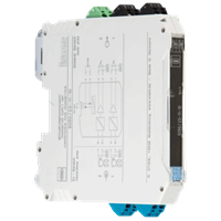
Transmitter Supply Unit Series 9260
Brand: R. STAHL AGSeries 9260 Ex i transmitter supply units can be used for the intrinsically safe operation of transmitters or intrinsically safe mA sources such as 4-wire transmitters.
The device allows HART signals to be transmitted in both directions.
The portfolio includes one- and two-channel devices and a variant for signal duplication.
Features- Universal use for transmitters and mA sources (4-wire transmitter)
- Slim design – 12.5 mm wide – for one- and two-channel versions
- Can be used for functional safety levels up to SIL 2 (IEC/EN 61508)
1 - 3 of 3 Part Numbers
261384
Universal use for transmitters and mA sources (4-wire transmitter)
Slim design – 12.5 mm wide – for one- and two-channel versions
Can be used for functional safety levels up to SIL 2 (IEC/EN 61508)
Ambient Conditions
- Ambient temperature - -20 °C ... +60 °C
- Ambient temperature max. - +60 °C
- Ambient temperature min. - -20 °C
- Electromagnetic compatibility - EN 61326-1 Use in industrial environment Immunity according to EN 61000-6-2 Interference emission to EN 61000-6-4
- Relative humidity max. - 10 to 95%
- Storage temperature - -40 °C ... +80 °C
- Storage temperature max. - +80 °C
- Storage temperature min. - -40 °C
- Use at the height of - < 2000 m
Auxiliary power
- Auxiliary power - 24 V DC
- Auxiliary power nom. voltage - 24 V DC
- Auxiliary power voltage range - 19,2 … 30 V
- Nominal current - 76.00 mA
- Operation indication - Green "PWR" LED
- Polarity reversal protection - yes
- Power consumption - 1.80 W
- Power dissipation max. - 1.20 W
Electrical Data
- communication signal - HART
- Isolating repeater mode - Yes
- Number of channels - 1
- Transmitter supply mode - Yes
Explosion Protection
- Application range (zones) - 2, 22
- ATEX dust certificate - BVS 17 ATEX E 087 X
- ATEX firedamp certificate - BVS 17 ATEX E 087 X
- ATEX gas certificate - BVS 17 ATEX E 087 X
- Certificates - ATEX (BVS), Canada / USA (UL), IECEx (BVS), SIL (BVS)
- Dust explosion protection ATEX - II (1) D [Ex ia Da] IIIC
- Dust explosion protection IECEx - [Ex ia Da] IIIC
- Ex interface in Division NEC 500 - (Class I, II, III) 1, 2
- Ex interface zone - 0, 1, 2, 20, 21, 22
- Firedamp protection ATEX - I (M1) [Ex ia Ma] I
- Firedamp protection IECEx - [Ex ia Ma] I
- Gas explosion protection ATEX - II 3 (1) G Ex nA [ia Ga] IIC T4 Gc
- Gas explosion protection IECEx - Ex nA [ia Ga] IIC T4 Gc
- IECEX dust certificate - IECEx BVS 17.0079X
- IECEx firedamp certificate - IECEx BVS 17.0079X
- IECEX gas certificate - IECEx BVS 17.0079X
- Installation in Division NEC 500 - (Class I, II, III) 2
Galvanic isolation
- Galvanic isolation Ex i input to auxiliary power - 375 V peak value
- Galvanic isolation Ex i input to output - 375 V peak value
- Galvanic isolation output to auxiliary power - 300 Veff
- Galvanic isolation output to output - 300 Veff
- Test voltage according to standard - IEC EN 60079-11
- Test voltage according to standard 2 - EN 61010 / EN 50178
General
- Functional Description - Series 9260 Ex i transmitter supply units can be used for the intrinsically safe operation of transmitters or intrinsically safe mA sources such as 4-wire transmitters. The device allows HART signals to be transmitted in both directions. The portfolio includes one- and two-channel devices and a variant for signal duplication.
- Highlights - Universal use for transmitters and mA sources (4-wire transmitter) Slim design – 12.5 mm wide – for one- and two-channel versions Can be used for functional safety levels up to SIL 2 (IEC/EN 61508)
- Product Description - Transmitter supply unit Ex i field circuit
- Product Type - 9260/13-11-10s
- Title Product Variant Technical Data - 9260/13-11-10s transmitter supply unit
- WebCode - 9260A
Input
- Input - 0/4 - 20 mA
- Input function - Isolation amplifier Transmitter power unit
- Input functional range - 0 ... 24 mA
- input signal - 0/4 ... 20 mA with HART
- short-circuit current - ≥ 22,5 mA
- Supply voltage for transmitter - ≥ 16 V at 20 mA
- voltage drop - < 3,5 V
Mechanical Data
- Degree of protection (IP) - IP30
- Enclosure material - Polyamide
- Fire resistance (UL 94) - V0
- Grid dimension - 12.50 mm
- Terminal degree of protection (IP) - IP20
- Weight - 0.185 kg
Mounting / Installation
- Conduct cross-section flexible max. - 0.2 mm²
- Conduct cross-section flexible max. - 2.5 mm²
- Conductor cross-section solid max. - 2.5 mm²
- Conductor cross-section solid min. - 0.2 mm²
- Connection type - Screw terminal
- Mounting position - vertical horizontal
- Mounting type - NS35/15, NS35/7.5 DIN rail
Output
- Behaviour of the output - = input signal
- deviation - ≤ 0,1 %
- LFD relay - No
- Load resistance R L max. - 1000.00 Ω
- Output - 0/4 ... 20 mA with HART
- Output A - 0/4 ... 20 mA
- Output current at I e =0 - 0 mA
- Output functional range - 0.0 - 24.0 mA
- Output residual ripple - < 20 mVeff
- output signal - 0/4 ... 20 mA active / passive
- Output version (control) - 0/4 ... 20 mA active / passive with HART
- Settling time 10 … 90 % - < 200 µs
- settling time note - Isolating repeater: < 600 µs
- Temperature influence error limits - < 0.1% / 10 K
- typical deviation - 0.05 %
Safety Data
- Internal capacitance C i - negligible
- Internal capacitance C i isolating repeater - negligible
- Internal inductance L i - negligible
- Internal inductance L i isolating repeater - negligible
- Max. current I i - 150.0 mA
- Max. Current I o - 93.0 mA
- Max. permissible external capacitance C o for IIB - 0.820 μF
- Max. permissible external capacitance C o for IIC - 0.107 μF
- Max. permissible external inductance L o for IIB - 4.000 mH
- Max. permissible external inductance L o for IIC - 2.000 mH
- Max. Power P o - 587.000 mW
- Max. voltage U i - 30.0 V
- Max. Voltage U o - 25.20 V
- Safety-related maximum voltage - 253 V AC
261385
Universal use for transmitters and mA sources (4-wire transmitter)
Slim design – 12.5 mm wide – for one- and two-channel versions
Can be used for functional safety levels up to SIL 2 (IEC/EN 61508)
Ambient Conditions
- Ambient temperature - -20 °C ... +60 °C
- Ambient temperature max. - +60 °C
- Ambient temperature min. - -20 °C
- Electromagnetic compatibility - EN 61326-1 Use in industrial environment Immunity according to EN 61000-6-2 Interference emission to EN 61000-6-4
- Relative humidity max. - 10 to 95%
- Storage temperature - -40 °C ... +80 °C
- Storage temperature max. - +80 °C
- Storage temperature min. - -40 °C
- Use at the height of - < 2000 m
Auxiliary power
- Auxiliary power - 24 V DC
- Auxiliary power nom. voltage - 24 V DC
- Auxiliary power voltage range - 19,2 … 30,0 V
- Nominal current - 75.00 mA
- Operation indication - Green "PWR" LED
- Polarity reversal protection - yes
- Power consumption - 1.80 W
- Power dissipation max. - 1.45 W
Electrical Data
- communication signal - HART
- Isolating repeater mode - Yes
- Number of channels - 1
- Transmitter supply mode - Yes
Explosion Protection
- Application range (zones) - 2, 22
- ATEX dust certificate - BVS 17 ATEX E 089 X
- ATEX gas certificate - BVS 17 ATEX E 089 X
- Certificates - ATEX (BVS), Canada / USA (UL), IECEx (BVS), SIL (BVS)
- Dust explosion protection ATEX - II (1) D [Ex ia Da] IIIC
- Dust explosion protection IECEx - [Ex ia Da] IIIC
- Ex interface in Division NEC 500 - (Class I, II, III) 1, 2
- Ex interface zone - 0, 1, 2, 20, 21, 22
- Gas explosion protection ATEX - II 3 (1) G Ex nA [ia Ga] IIC T4 Gc
- Gas explosion protection IECEx - Ex nA [ia Ga] IIC T4 Gc
- IECEX dust certificate - IECEx BVS 17.0081X
- IECEX gas certificate - IECEx BVS 17.0081X
- Installation in Division NEC 500 - (Class I, II, III) 2
Galvanic isolation
- Galvanic isolation Ex i input to auxiliary power - 375 V peak value
- Galvanic isolation Ex i input to output - 375 V peak value
- Galvanic isolation output to auxiliary power - 300 Veff
- Galvanic isolation output to output - 300 Veff
- Test voltage according to standard - IEC EN 60079-11
- Test voltage according to standard 2 - EN 61010 / EN 50178
General
- Functional Description - Series 9260 Ex i transmitter supply units can be used for the intrinsically safe operation of transmitters or intrinsically safe mA sources such as 4-wire transmitters. The device allows HART signals to be transmitted in both directions. The portfolio includes one- and two-channel devices and a variant for signal duplication.
- Highlights - Universal use for transmitters and mA sources (4-wire transmitter) Slim design – 12.5 mm wide – for one- and two-channel versions Can be used for functional safety levels up to SIL 2 (IEC/EN 61508)
- Product Description - Transmitter supply unit Ex i field circuit
- Product Type - 9260/19-11-10s
- Title Product Variant Technical Data - 9260/19-11-10s transmitter supply unit
- WebCode - 9260A
Input
- Input - 0/4 - 20 mA
- Input function - Isolation amplifier Transmitter power unit
- Input functional range - 0 ... 24 mA
- input signal - 0/4 ... 20 mA with HART
- short-circuit current - ≥ 22,5 mA
- Supply voltage for transmitter - ≥ 16 V at 20 mA
- voltage drop - < 3,5 V
Mechanical Data
- Degree of protection (IP) - IP30
- Enclosure material - Polyamide
- Fire resistance (UL 94) - V0
- Grid dimension - 12.50 mm
- Terminal degree of protection (IP) - IP20
- Weight - 0.195 kg
Mounting / Installation
- Conduct cross-section flexible max. - 0.2 mm²
- Conduct cross-section flexible max. - 2.5 mm²
- Conductor cross-section solid max. - 2.5 mm²
- Conductor cross-section solid min. - 0.2 mm²
- Connection type - Screw terminal
- Mounting position - horizontal vertical
- Mounting type - NS35/15, NS35/7.5 DIN rail
Output
- Behaviour of the output - = input signal
- deviation - ≤ 0,1 %
- LFD relay - No
- Load resistance R L max. - 450.00 Ω
- Output - 0/4 ... 20 mA with HART
- Output A - 0/4 ... 20 mA
- Output B - 0/4 ... 20 mA (without HART)
- Output current at I e =0 - 0 mA
- Output functional range - 0.0 - 24.0 mA
- Output residual ripple - < 20 mVeff
- output signal - 0/4 ... 20 mA active
- Output version (control) - 0/4 ... 20 mA active / with HART
- Settling time 10 … 90 % - < 200 µs
- settling time note - Isolating repeater: < 600 µs
- Temperature influence error limits - < 0.1% / 10 K
- typical deviation - 0.05 %
Safety Data
- Internal capacitance C i - negligible
- Internal capacitance C i isolating repeater - negligible
- Internal inductance L i - negligible
- Internal inductance L i isolating repeater - negligible
- Max. current I i - 150.0 mA
- Max. Current I o - 93.0 mA
- Max. permissible external capacitance C o for IIB - 0.820 μF
- Max. permissible external capacitance C o for IIC - 0.107 μF
- Max. permissible external inductance L o for IIB - 4.000 mH
- Max. permissible external inductance L o for IIC - 2.000 mH
- Max. Power P o - 587.000 mW
- Max. voltage U i - 30.0 V
- Max. Voltage U o - 25.20 V
- Safety-related maximum voltage - 253 V AC
261386
Universal use for transmitters and mA sources (4-wire transmitter)
Slim design – 12.5 mm wide – for one- and two-channel versions
Can be used for functional safety levels up to SIL 2 (IEC/EN 61508)
Ambient Conditions
- Ambient temperature - -20 °C ... +60 °C
- Ambient temperature max. - +60 °C
- Ambient temperature min. - -20 °C
- Electromagnetic compatibility - EN 61326-1 Use in industrial environment Immunity according to EN 61000-6-2 Interference emission to EN 61000-6-4
- Relative humidity max. - 10 to 95%
- Storage temperature - -40 °C ... +80 °C
- Storage temperature max. - +80 °C
- Storage temperature min. - -40 °C
- Use at the height of - < 2000 m
Auxiliary power
- Auxiliary power - 24 V DC
- Auxiliary power nom. voltage - 24 V DC
- Auxiliary power voltage range - 19,2 … 30,0 V
- Nominal current - 100.00 mA
- Operation indication - Green "PWR" LED
- Polarity reversal protection - yes
- Power consumption - 2.40 W
- Power dissipation max. - 1.45 W
Electrical Data
- communication signal - HART
- Isolating repeater mode - No
- Number of channels - 2
- Transmitter supply mode - Yes
Explosion Protection
- Application range (zones) - 2, 22
- ATEX dust certificate - BVS 17 ATEX E 090 X
- ATEX gas certificate - BVS 17 ATEX E 090 X
- Certificates - ATEX (BVS), Canada / USA (UL), IECEx (BVS), SIL (BVS)
- Dust explosion protection ATEX - II (1) D [Ex ia Da] IIIC
- Dust explosion protection IECEx - [Ex ia Da] IIIC
- Ex interface in Division NEC 500 - (Class I, II, III) 1, 2
- Ex interface zone - 0, 1, 2, 20, 21, 22
- Gas explosion protection ATEX - II 3 (1) G Ex nA [ia Ga] IIC T4 Gc
- Gas explosion protection IECEx - Ex nA [ia Ga] IIC T4 Gc
- IECEX dust certificate - IECEx BVS 17.0082X
- IECEX gas certificate - IECEx BVS 17.0082X
- Installation in Division NEC 500 - (Class I, II, III) 2
Galvanic isolation
- Galvanic isolation Ex i input to auxiliary power - 375 V peak value
- Galvanic isolation Ex i input to output - 375 V peak value
- Galvanic isolation output to auxiliary power - 300 Veff
- Galvanic isolation output to output - 300 Veff
- Test voltage according to standard - IEC EN 60079-11
- Test voltage according to standard 2 - EN 61010 / EN 50178
General
- Functional Description - Series 9260 Ex i transmitter supply units can be used for the intrinsically safe operation of transmitters. The device allows HART signals to be transmitted in both directions. The portfolio includes one- and two-channel devices and a variant for signal duplication.
- Highlights - Universal use for transmitters Slim design – 12.5 mm wide – for one- and two-channel versions Can be used for safety levels up to SIL 2 (IEC/EN 61508)
- Product Description - Transmitter supply unit Ex i field circuit
- Product Type - 9260/23-11-10s
- Title Product Variant Technical Data - 9260/23-11-10s transmitter supply unit
- WebCode - 9260A
Input
- Input - 4 - 20 mA
- Input function - Transmitter power unit
- Input functional range - 0 ... 24 mA
- input signal - 4 ... 20 mA with HART
- short-circuit current - ≥ 22,5 mA
- Supply voltage for transmitter - ≥ 16 V at 20 mA
Mechanical Data
- Degree of protection (IP) - IP30
- Enclosure material - Polyamide
- Fire resistance (UL 94) - V0
- Grid dimension - 12.50 mm
- Terminal degree of protection (IP) - IP20
- Weight - 0.195 kg
Mounting / Installation
- Conduct cross-section flexible max. - 0.2 mm²
- Conduct cross-section flexible max. - 2.5 mm²
- Conductor cross-section solid max. - 2.5 mm²
- Conductor cross-section solid min. - 0.2 mm²
- Connection type - Screw terminal
- Mounting position - horizontal vertical
- Mounting type - NS35/15, NS35/7.5 DIN rail
Output
- Behaviour of the output - = input signal
- deviation - ≤ 0,1 %
- LFD relay - No
- Load resistance R L max. - 450.00 Ω
- Output - 4 ... 20 mA with HART
- Output A - 4 ... 20 mA
- Output B - 4 ... 20 mA
- Output current at I e =0 - 0 mA
- Output functional range - 0.0 - 24.0 mA
- Output residual ripple - < 20 mVeff
- output signal - 4 ... 20 mA active
- Output version (control) - 0/4 ... 20 mA active / with HART
- Settling time 10 … 90 % - < 200 µs
- Temperature influence error limits - < 0.1% / 10 K
- typical deviation - 0.05 %
Safety Data
- Internal capacitance C i - negligible
- Internal inductance L i - negligible
- Max. Current I o - 93.0 mA
- Max. permissible external capacitance C o for IIB - 0.820 μF
- Max. permissible external capacitance C o for IIC - 0.107 μF
- Max. permissible external inductance L o for IIB - 4.000 mH
- Max. permissible external inductance L o for IIC - 2.000 mH
- Max. Power P o - 587.000 mW
- Max. Voltage U o - 25.20 V
- Safety-related maximum voltage - 253 V AC
1 - 3 of 3 Part Numbers