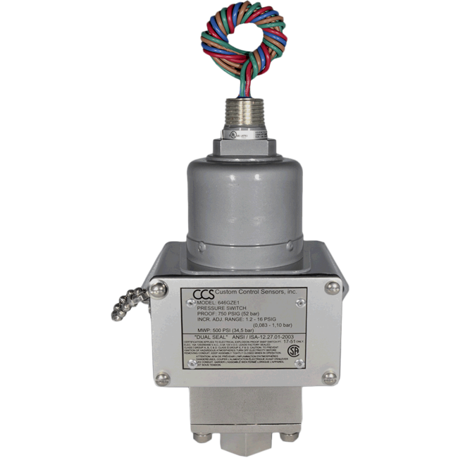
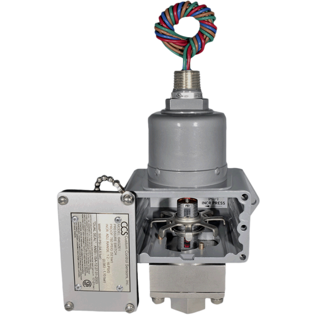
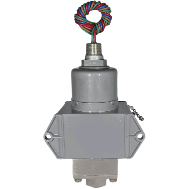
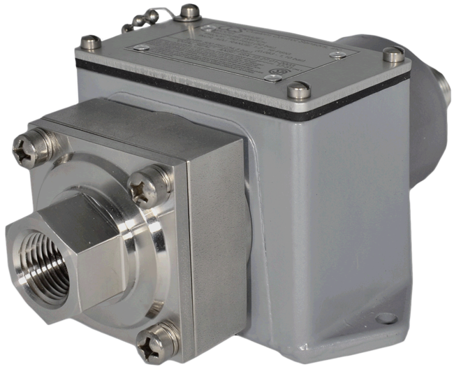
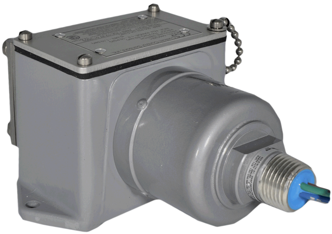
646GZE-7011 Series Pressure Switch
Brand: Custom Control Sensors, LLC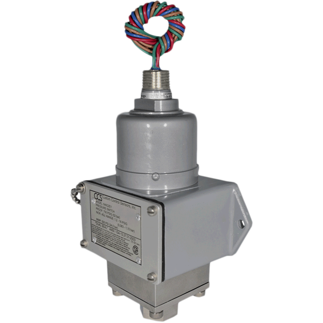
- Adjustable Set Point Range
- Increasing
- psig 1.4 - 5000
- kPa 9.65 - 34,473.79
- bar 0.09 - 344.7
- Decreasing
- psig 0.4 - 4520
- kPa 2.76 - 31,164.30
- bar 0.03 - 311.6
- Increasing
- Deadband - Approximate: 1 - 480 psig, 6.9 - 3309.48 kPa, 0.07 - 33.1 bar
- System Pressure - Maximum: 500 - 5000 psig, 3447.38 - 34,473.79 kPa, 35 - 345 bar
- Proof Pressure: 750 - 7500 psig, 5171.07 - 51,710.68 kPa, 52 - 517 bar
- Wetted Materials
- Pressure Port: 1/2" Female NPT 316 Stainless Steel
- O-Ring: Viton
- Relay: SPDT or DPDT
- UL, CSA
- Explosion Proof - Class 1, Div/Zone 1, Groups A, B, C and D
- CE Mark, CRN, Dual Seal, NACE
646GCEMY10-7011
- Adjustable Set Point Range
- Increasing
- psig 3200 - 5000
- Decreasing
- psig 2720 - 4520
- Increasing
- Deadband - Approximate: 480 psig
- System Pressure - Maximum: 5000 psig
- Proof Pressure: 7500 psig
- Wetted Materials
- Pressure Port: 1/2" FNPT 316 Stainless Steel Welded Capsule
- Relay: DPDT
- ATEX
- ATEX Certified For Potentially Explosive Atmospheres Electrical Assembly Series
- 46-XXXXXXX, Models 6*****, Ex d IIC T6, Directive 94/9/EC Sira #08ATEX 1046X (Option Y)
- IECEx - SIRA Certified, SIR 10,0193X (Option Y)
- CE Mark, CRN
646GCEMY9-7011
646GZE10-7011
- Adjustable Set Point Range
- Increasing
- psig 3200 - 5000
- kPa 22063.3 - 34,473.7
- bar 220.6 - 344.7
- Decreasing
- psig 2720 - 4520
- kPa 18,753.8 - 31,164.3
- bar 187.5 - 311.6
- Increasing
- Deadband - Approximate: 480 psi, 3309.48 kPa, 33.1 bar
- System Pressure - Maximum: 5000 psig, 34,473.78 kPa, 345 bar
- Proof Pressure: 7500 psig, 51,710.68 kPa, 517 bar
- Wetted Materials
- Pressure Port: 1/2" FNPT 316 Stainless Steel
- Diaphragm: 316 Stainless Steel
- O-Ring: Viton
- Relay: SPDT
- UL, CSA
- Explosion Proof - Class 1, Div/Zone 1, Groups A, B, C and D
- CRN, CE Mark, NACE
646GZE10-7011IN
646GZE10-7023
- Base Model - 646GZE10-7011
- Process Connection - 1/2"-14 Female NPT 316 Stainless Steel
- Diaphragm - 316 Stainless Steel
- O-Ring - Viton
- Output - SPDT
- Electrical Contacts - Silver
- Electrical - Free Leads - 18" (45 cm) Free Leads - Standard Hazardous
- Agency Approvals - UL, CSA, CE, CRN, Dual Seal
- Paint - Standard Finish
646GZE10-7023-7034
- Base Model - 646GZE10-7011
- Process Connection - 1/2"-14 Female NPT 316 Stainless Steel
- Diaphragm - 316 Stainless Steel
- O-Ring - Viton
- Output - SPDT
- Electrical Contacts - Silver
- Electrical - Free Leads - 18" (45 cm) Free Leads - Standard Hazardous
- Agency Approvals - UL, CSA, CE, CRN, Dual Seal
- Paint - Epoxy Paint
646GZE10-7030
- Base Model - 646GZE10-7011
- Process Connection - 1/2"-14 Female NPT 316 Stainless Steel
- Diaphragm - 316 Stainless Steel
- O-Ring - Viton
- Output - SPDT
- Electrical Contacts - Gold Contacts - SPDT
- Electrical - Free Leads - 18" (45 cm) Free Leads - Standard Hazardous
- Agency Approvals - UL, CSA, CE, CRN, Dual Seal
- Paint - Standard Finish
646GZE10-7030-7034
- Base Model - 646GZE10-7011
- Process Connection - 1/2"-14 Female NPT 316 Stainless Steel
- Diaphragm - 316 Stainless Steel
- O-Ring - Viton
- Output - SPDT
- Electrical Contacts - Gold Contacts - SPDT
- Electrical - Free Leads - 18" (45 cm) Free Leads - Standard Hazardous
- Agency Approvals - UL, CSA, CE, CRN, Dual Seal
- Paint - Epoxy Paint
646GZE10-7065
- Adjustable Set Point Range
- Increasing
- psig 3200 - 5000
- kPa 22,063.3 - 34,473.7
- bar 220.6 - 344.7
- Decreasing
- psig 2720 - 4520
- kPa 18,753.8 - 31,164.3
- bar 187.5 - 311.6
- Increasing
- Deadband - Approximate: 480 psi, 3309.48 kPa, 33.1 bar
- System Pressure - Maximum: 5000 psig, 34,473.78 kPa, 345 bar
- Proof Pressure: 7500 psig, 51,710.68 kPa, 517 bar
- Wetted Materials
- Pressure Port: 1/2" FNPT 316 Stainless Steel
- Diaphragm: 316 Stainless Steel
- O-Ring: Viton
- Relay: SPDT
- Wire: Teflon
- UL, CSA
- Explosion Proof - Class 1, Div/Zone 1, Groups A, B, C and D
- CRN, CE Mark, NACE
646GZE10-7065-7034
- Base Model - 646GZE10-7011
- Process Connection - 1/2"-14 Female NPT 316 Stainless Steel
- Diaphragm - 316 Stainless Steel
- O-Ring - Viton
- Output - SPDT
- Electrical Contacts - Gold Contacts - SPDT
- Electrical - Free Leads - 18" (45 cm) Free Leads - Teflon for Low Temperatures (Hazardous)
- Agency Approvals - UL, CSA, CE, CRN, Dual Seal
- Paint - Epoxy Paint
646GZE10-7104
- Base Model - 646GZE10-7011
- Process Connection - 1/2"-14 Female NPT 316 Stainless Steel
- Diaphragm - 316 Stainless Steel
- O-Ring - Viton
- Output - SPDT
- Electrical Contacts - Gold Contacts - SPDT
- Electrical - Free Leads - 2 meter (6.5 Feet) Free Leads, Explosion-Proof
- Agency Approvals - UL, CSA, CE, CRN, Dual Seal
- Paint - Standard Finish
646GZE10-7104-7034
- Base Model - 646GZE10-7011
- Process Connection - 1/2"-14 Female NPT 316 Stainless Steel
- Diaphragm - 316 Stainless Steel
- O-Ring - Viton
- Output - SPDT
- Electrical Contacts - Gold Contacts - SPDT
- Electrical - Free Leads - 2 meter (6.5 Feet) Free Leads, Explosion-Proof
- Agency Approvals - UL, CSA, CE, CRN, Dual Seal
- Paint - Epoxy Paint
Specifications
Adjustment Type
- Field Adjustable
Approvals & Certifications
- ATEX
- CE
- CRN - Canadian Registration Number
- CRN - Alberta
- CRN - British Columbia
- CRN - Manitoba
- CRN - N.W. Territories
- CRN - Saskatchewan
- CSA
- cUL
- Dual Seal
- EMC
- LVD
- PED
- RoHS
- RTN
- UL
Deadband, Approximate
- bar: 0.07 - 33.1
- kPa: 6.9 - 3,309
- psig: 1 - 480
Diaphragm Material
- Stainless Steel
Electrical - Free Leads
- 18" (45 cm) Free Leads
- 18" (45 cm) Teflon Leadwire
Electrical Assembly
- Hermetic Seal
Electrical Certification
- ATEX - Baseefa Certified for Potentially Explosive Atmospheres. Models 646**Y, II 2 GD Ex d IIC, Ex Tb IIIC, Baseefa 05-ATEX-0011X. (Option Y)
- cUL, UL/CSA, Hazardous Areas, Div. 1, 2
Electrical Connectors
- 1/2" NPT Male
Electrical Contacts
- Gold
- Silver
Electrical Rating
- 1 A at 125 Vac, 50/60 Hz
- 11 A at 125/250 Vac Resistive, 5 A at 28 Vdc, 0.5 A at 125 Vdc
- 15 A at 125/250/480 Vac Resistive, 0.2 A at 250 Vdc
Enclosure, Body Material
- Aluminum
Environmental Protection
- Hazardous Area
- IP54
- IP66
- NEMA 13
- NEMA 4, 7, 9, 13 / IP54, 66
- NEMA 7
- NEMA 9
NACE & NIST
- NACE MR-0175: 2003
NPT Connection
- 1/2" NPT Female
O-Ring Material
- Ethylene Propylene (EPR)
- Viton
Operating Temperature
- -40° to 86° C
- -40° to 187° F
Process Connection Material
- 316 Stainless Steel
Proof Pressure
- bar: 51.7 - 517
- kPa: 5,171 - 51,711
- psig: 750 - 7,500
Service
- Sour (Oil & Gas)
Set Point - Decreasing
- bar: 0.03 - 312
- kPa: 2.8 - 31,164
- psig: 0.4 - 4,520
Set Point - Increasing
- bar: 0.09 - 345
- kPa: 9.7 - 34,473.7
- psig: 1.4 - 5,000
Switch Type
- DPDT
- SPDT
System Pressure
- bar: 34.5 - 345
- kPa: 3,447 - 34,474
- psig: 500 - 5,000
- Boilers & Burners
- Chemical & Petrochemical Plants
- Chemical Refining & Processing
- Degreasers & Evaporators
- Fluid Management
- Food Processing
- Ground Support Equipment
- Hydraulic & Lubrication Systems
- Heating & Air Conditioning
- Manufacturing Process
- Oil & Gas
- Pipelines
- Power Generation
- Power Plants
- Pulp & Paper Mills
- Pumps, Compressors & Turbines
- Recovery Systems
- Refineries
- Reverse Osmosis Systems & Filters
- Safety Systems
- Specialized OEM Equipment
- Steel Mills
- Utilities
- Water Treatment, Waste & Sewage Treatment Facilities
646GZE-7011 Series Pressure Switch
- Introduction
- Fundamentals of Pressure Switch Technology
- DualSnap™ Principle
- 646GZE-7011: Product Overview
- Key Features and Advantages
- Mechanical Construction and Design
- Technical Specifications
- Common Industry Applications
- Pre-Installation Considerations
- Mounting and Mechanical Installation
- Electrical Configuration and Outputs
- Calibration and Adjustment Procedures
- Integration with Plant Control Systems
- Operational Factors and Challenges
- Maintenance, Inspection, and Cleaning
- Troubleshooting and Diagnostics
- Safety, Regulatory Standards, and Certifications
- Comparisons with Other Pressure Switch Technologies
- Case Studies and Practical Implementations
- Best Practices for Long-Term Reliability
- Future Trends in Pressure Switch Technology
- Conclusion
1. Introduction
Controlling and monitoring process pressures is a critical element of industrial plant operations in fields such as petrochemicals, power generation, food and beverage, and general manufacturing. Whether protecting equipment from overpressure, ensuring pumps switch on at a defined setpoint, or signaling alarms for low-pressure conditions, a robust and accurate pressure switch is indispensable for safe, efficient processes. Mechanical pressure switches, in particular, remain popular for their simplicity, reliability, and independence from external power for sensing.
The CCS DualSnap™ 646GZE-7011 stands out among mechanical pressure switches due to Dual-Snap technology, which provides extremely stable, snap-action operation with minimal drift over time. Combining a well-sealed enclosure, adjustable setpoints, and proven design, the 646GZE-7011 model is well-suited for critical applications where repeatable, consistent performance is paramount. This extensive description offers plant operators a thorough understanding of how the switch works, how to install and calibrate it, how to maintain it for extended life, and how to integrate it into diverse industrial control systems.
2. Fundamentals of Pressure Switch Technology
2.1 Basic Principle
A pressure switch detects changes in fluid or gas pressure and actuates an electrical contact when the measured pressure crosses a preset threshold. Traditionally, mechanical pressure switches contain:
- Sensing Element: A diaphragm, piston, or bellows that deflects under applied pressure.
- Linkage or Spring Mechanism: Translates sensor deflection into movement toward an internal switch.
- Adjustable Setpoint: A calibration spring allows the user to define the pressure at which the electrical contact toggles from open to closed (or vice versa).
- Output Contacts: Usually single-pole, double-throw (SPDT) or similar, enabling on/off signals for alarms or control circuits.
2.2 Differentiating Mechanical from Electronic
- Mechanical Switches: Operate purely on mechanical deflection and internal linkages. They do not require power for detection (only for switching output signals), are cost-effective, and are robust in a wide range of environments.
- Electronic Transmitters: Provide continuous analog or digital signals, but are more complex, require supply power, and can be more expensive.
2.3 Applications of Pressure Switches
From ensuring pumps engage at a low-pressure threshold in water systems, to preventing overpressure in compressors or hydraulic lines, mechanical pressure switches are ubiquitous. They serve as protective interlocks, alarm triggers, or input signals to PLC or DCS systems.
3. DualSnap™ Principle
3.1 Snap-Action Mechanism
CCS DualSnap™ technology uses a snap-action disc spring or Belleville spring arrangement that provides:
- Consistent Switching: Minimizes setpoint drift over repeated cycles.
- High Overpressure Tolerance: The disc spring can endure transient spikes without permanent deformation.
- Precision: Once the threshold is reached, the snap disc changes state abruptly, reducing contact chatter and improving repeatable performance.
3.2 Advantages of DualSnap
- Reduced Wear: The quick snap to open or close the electrical circuit helps mitigate micro-arcing on the contacts, prolonging switch life.
- Stable Setpoints: Minimizes hysteresis drift over time, essential in critical safety or control circuits.
- Minimal Overtravel: The disc moves only slightly beyond setpoint, limiting mechanical stress on the sensor elements.
4. 646GZE-7011: Product Overview
4.1 Purpose and Use Cases
The 646GZE-7011 is a pressure switch designed for processes requiring robust, accurate setpoints and minimal drift over repeated cycles. It toggles an electrical circuit once the monitored pressure meets or exceeds the user-defined threshold. Common roles:
- Overpressure Shutoff: Protecting equipment from high-pressure damage.
- Low-Pressure Alarm: Triggering reorder or halting machinery to avoid pump cavitation or incomplete process operations.
- Intermediate Pressure Control: Serving as an interlock or enabling multi-stage operations in processes that rely on distinct pressure steps.
4.2 Key Specifications in Context
Often, the 646GZE-7011 can handle broad pressure ranges (like 3–5,000 PSI or more, depending on the exact sub-model). It typically includes:
- Adjustable Setpoint: Letting operators fine-tune the trip pressure to match the process requirements.
- SPDT or DPDT Contacts: Possibly up to certain voltage and current ratings (~5 A @ 250 V AC, for example).
- Sealed Enclosure: Suitable for outdoor or harsh industrial placements, possibly meeting NEMA or IP classifications (e.g., NEMA 4X, IP65).
- Wide Temperature Range: Operating from subfreezing to significantly high ambient or process temperatures, within reason.
5. Key Features and Advantages
5.1 DualSnap™ Snap-Action Disc
The hallmark of CCS pressure switches, ensuring:
- Crisp, Quick Switching: Minimizes contact arcing, extending switch contact life.
- High Repeat Accuracy: Typically ±1 or 2% of range, or better, depending on model.
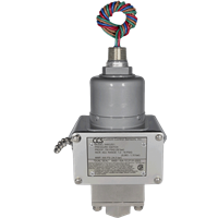
5.2 Rugged Enclosure
- Sealed Against Moisture and Dust: The 646GZE-7011 typically meets or exceeds industrial environmental ratings, like NEMA 4 or 4X for washdown or corrosive atmospheres.
- Corrosion-Resistant Materials: May feature stainless steel or anodized aluminum housings in some variations.
5.3 Adjustable Setpoints
Often featuring an external or internal adjustment screw. Operators can calibrate the switch to trigger at a specified pressure. Some models include a scale or pointer, though for precise calibration, a reference gauge or test rig is recommended.
5.4 Contact Ratings
SPDT contacts handle moderate current (often up to ~5 A at 250 V AC for resistive loads), suitable for direct control of small pumps or solenoids, or signal input to a PLC or alarm circuit.
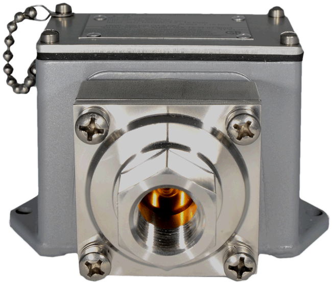
6. Mechanical Construction and Design
6.1 Pressure Sensing Element
The 646GZE-7011 typically includes a diaphragm or piston subassembly. The process pressure acts on this diaphragm or piston, transferring force to the snap-action disc. Materials can be stainless steel, elastomers, or specialized alloys for higher temperature or chemical compatibility.
6.2 Snap Disc / Belleville Spring
A dual snap disc provides the quick transition between open and closed states, ensuring minimal drift:
- Preloaded Spring: The spring is loaded to a certain baseline, shifting rapidly once the input pressure crosses the set threshold.
- Hysteresis: Usually small, preventing switch chatter near the setpoint.
6.3 Enclosure and Port
- Pressure Port: Typically 1/4" NPT or other standard threads for hooking to the process line or manifold.
- Cover: Sealed to keep out dust, moisture, or chemicals, possibly featuring an O-ring or gasket arrangement.
7. Common Industry Applications
7.1 Oil and Gas
Used for overpressure protection in pipelines, wellheads, or process lines. The robust sealing ensures stable operation in harsh, possibly explosive environments.
7.2 Power Generation
Monitoring steam line or auxiliary feedwater pressures, ensuring pumps start or stop at set thresholds to maintain system integrity.
7.3 Chemical Processing
From reacting vessels to storage tanks, consistent pressure triggers allow for stable batch operations or safety interlocks.
7.4 Food and Beverage
Ensuring CIP (clean-in-place) lines or processing vessels do not exceed safe pressure levels. The sealed design fosters use in washdown areas.
7.5 General Manufacturing
Compressors, hydraulic presses, or pneumatic lines rely on mechanical pressure switches to stop or start equipment, guaranteeing stable pressure supply or overpressure shutoff.
8. Pre-Installation Considerations
8.1 Determine Pressure Range
Ensure the 646GZE-7011’s specified range accommodates your expected normal operating pressure plus potential surges or spikes. If near the top of the sensor’s range, consider a higher range model to maintain setpoint stability.
8.2 Media Compatibility
Check the sensor’s diaphragm or piston material for chemical compatibility with the process fluid or gas. For harsh chemicals or corrosives, stainless steel or specialized coatings may be required.
8.3 Temperature Environment
If ambient or process temperature exceeds sensor’s rating, consider cooling loops, standoffs, or high-temperature variants. Extended exposure above rated temperatures can degrade the snap-action disc or elastomer seals.
8.4 Pressure Port and Mounting
Confirm the process connection (often 1/4" NPT) aligns with your piping or manifold. Plan for enough clearance to access the adjustment screw or to remove the sensor for calibration.
9. Mounting and Mechanical Installation
9.1 Orientation
Most mechanical pressure switches are orientation-insensitive, but verifying the recommended orientation can help. Typically upright or horizontal mounting is standard:
- Vertical: Minimizing stress on internal linkages.
- Horizontal: If environment or piping layout demands it.
9.2 Pipe or Manifold Connection
- Threaded: Use suitable thread sealant (PTFE tape or paste) that is chemical-compatible.
- Torque: Do not overtighten, as excessive torque can deform sensor threads or cause alignment issues.
9.3 Vibration Concerns
If the environment has high vibration or pulsations, consider installing a dampening mechanism (like a snubber or flexible hose) or ensure the switch is bracketed to reduce mechanical shock.
9.4 Access for Adjustment
Ensure the switch’s setpoint adjustment mechanism is reachable. If the switch has an external adjustment screw, leave enough space for a small wrench or hex key. For internal adjustments, the cover must be removable.
10. Electrical Configuration and Output Integration
10.1 Output Contacts
The SPDT micro-switch typically includes:
- Common (C)
- Normally Open (NO)
- Normally Closed (NC)
Depending on desired logic, you wire to either NO or NC relative to the common.
10.2 Voltage/Current Ratings
Check the contact rating:
- AC: Possibly up to ~250 V AC, ~5 A.
- DC: Lower DC current rating often, e.g., ~1–2 A at 30 V DC.
Exceeding these limits can cause arcing or short switch life.
10.3 Grounding/Earthing
In dusty or explosive zones, or for general safety, the sensor housing might require earthing. Ensure the device’s ground terminal is properly bonded to plant ground potential.
10.4 PLC vs. Direct Control
- PLC Digital Input: Often the sensor’s relay lines feed the PLC for alarm or interlock logic.
- Local Alarm Circuit: Alternatively, the switch can directly power a lamp or small relay coil, so long as current ratings are respected.
11. Calibration and Adjustment Procedures
11.1 Factory Setpoint
Some 646GZE-7011 units arrive with a standard factory setpoint. However, operators typically need to calibrate the switch to a process-specific value:
- Connect to a Pressure Test Rig: Provide known, stable test pressures.
- Observe Switch Activation: Adjust the setpoint screw or spring tension until the micro-switch changes state at the target pressure.
- Check Deadband: The difference between switch-on and switch-off points. Minor adjustments can refine hysteresis if needed.
11.2 External vs. Internal Adjustments
Some designs feature an external adjustment accessible via a small screw outside the enclosure. Others require removing a cover to access an internal adjusting mechanism. Follow recommended torque or turning increments, typically listed in the manual.
11.3 Final Verification
After adjusting:
- Pressurize above the setpoint. Confirm the switch toggles “covered.”
- Depressurize below the setpoint. Confirm it toggles “uncovered.”
- Document the final setpoint and date for future reference or re-calibration schedules.
12. Integration with Plant Control Systems
12.1 PLC or SCADA Logic
Program the PLC rung logic or SCADA threshold to interpret the switch’s NO/NC lines. For high-level or overpressure alarms, a latched or momentary approach might be used:
- Latched Alarms: Requiring operator intervention to reset.
- Momentary: Alerts triggered while coverage persists.
12.2 Hysteresis or Delay in Control Logic
If system pressure cycles near the setpoint, repeated toggling can occur. The PLC or SCADA might incorporate a short time delay or a small hysteresis zone to avoid chatter.
12.3 Safety Interlocks
Critical processes (steam lines, high-pressure vessels) may use the RN 646GZE-7011 sensor in tandem with other safety instruments (pressure relief valves, other sensors) to ensure multi-layer protection.
13. Operational Factors and Challenges
13.1 Pressure Pulsations
Rapid cycling or pulsating lines can cause frequent toggles or micro-switch wear. Installing a pulsation dampener or snubber can help protect the sensor’s internal mechanism from excessive mechanical stress.
13.2 Temperature Extremes
Extended operation above the sensor’s rating can degrade diaphragm/piston seals or the snap disc. Ensure temperature remains within specification or consider optional high-temp variants or standoffs.
13.3 Corrosion or Fouling
If the measured medium is corrosive or heavily contaminated, choose suitable wetted materials (stainless steels, specialized coatings) and consider placing the sensor in a location less prone to buildup. Regularly verify no solids accumulate in the sensor port.
14. Maintenance, Inspection, and Cleaning
14.1 Maintenance Overview
While mechanical pressure switches require minimal day-to-day care, monthly or quarterly inspections ensure:
- Port Cleanliness: No clogging or debris restricting the process pressure from reaching the sensor.
- Setpoint Consistency: Pressure rig checks can verify if the switch toggles near the intended threshold.
- Enclosure Seal: Confirm IP or NEMA rating is intact, with no cracks or loose cable glands.
14.2 Overhaul or Replacement
If the snap disc or internal components degrade after extensive cycles, the entire switch might be replaced. If a part is user-serviceable (like a diaphragm or micro-switch), follow the official procedure to maintain certification.
14.3 Calibration Interval
Though stable, many plants schedule annual or biennial calibration checks. Document calibration results to track drift over time. The DualSnap disc design typically exhibits minimal drift, but verifying setpoint accuracy is prudent for critical processes.
15. Troubleshooting and Diagnostics
15.1 Switch Does Not Toggle
- Clogged Port: Material or debris blocks pressure from reaching the sensor.
- Wrong Range: The sensor’s range is below or above actual line pressure.
- Damaged Micro-Switch: Possibly from over-voltage or mechanical stress.
- No Mechanical Deflection: Diaphragm or piston jammed, or snap disc damaged from overpressure.
15.2 Drift from Original Setpoint
- Wear or Fatigue: The spring or disc has lost tension over repeated cycles.
- Temperature Effects: Extreme ambient or process temperature can cause minor shifts in setpoint.
- Vibration: Could cause the adjusting screw to back out if not properly locked.
15.3 Frequent False Tripping
- Pulsating Pressure: Rapid cycles near setpoint cause chatter. Add a snubber or adjust hysteresis if possible.
- Excessive Temperature: Slight internal expansion might cause spurious toggling near the threshold.
- Noise in the Circuit: Relay coil or wiring issues might produce false on/off signals to the PLC.
16. Safety and Regulatory Standards
16.1 Hazardous Areas
For dust or gas explosive atmospheres, the sensor must carry ATEX/IECEx or region-specific certifications (e.g., CSA, UL for North America). Inspect the nameplate for zone or division rating.
16.2 Electrical Code Compliance
Implement local/national standards (NEC, IEC). This includes:
- Conduit Requirements
- Overcurrent Protection
- Earthing
16.3 Lockout/Tagout
When adjusting or removing the switch from a pressurized line, ensure the line is depressurized, or isolate the sensor port. Follow site lockout/tagout rules for the electrical supply.
17. Comparisons with Other Pressure Switch Technologies
17.1 Diaphragm vs. Piston vs. Bellows
The internal mechanism (diaphragm or piston) can vary. The 646GZE-7011 likely uses a diaphragm-based or piston-based approach. Each suits different pressure ranges:
- Diaphragm: Good for lower pressure ranges or broad temperature spans.
- Piston: Often for higher pressures, though typically with small displacement.
17.2 Electronic Pressure Transmitters
Transmitters provide continuous 4–20 mA or digital signals. While more flexible for advanced process control, they require power for sensing and are more expensive. A mechanical switch is simpler, cheaper, and can function without external power for the sensing aspect.
17.3 Other Mechanical Switches (e.g., “Live Spring”)
Some older mechanical designs lack the snap disc approach. The DualSnap technology provides a more stable and repeatable setpoint over time, minimizing drift.
18. Case Studies and Practical Implementations
18.1 Refinery Overpressure Protection
A petroleum refinery installed the 646GZE-7011 on multiple lines feeding into a fractionation tower. The sensor’s stable setpoint prevented minor pressure spikes from causing spurious alarms. Over a year, the setpoints remained within ±1% of the initial calibration, reducing downtime from false triggers.
18.2 Food Processing CIP Lines
A large dairy used the pressure switch to sense CIP line pressure. The unit endured daily washdowns, thanks to its sealed enclosure. Operators praised its consistent toggling near 50 PSI, ensuring CIP pumps engaged only when the line was pressurized.
18.3 Air Compressor Safety
In an industrial compressor system, the sensor monitored discharge line pressure to prevent over-compression. The DualSnap disc delivered crisp switching with minimal contact arcing, prolonging the micro-switch life and giving reliable overpressure alarms.
19. Best Practices for Long-Term Reliability
- Routine Calibration Checks: Annually verify setpoint with a known reference gauge.
- Clean Port: Inspect for plugging or material buildup.
- Lock Adjustment Screws: If a jam nut or locking device is present, secure after calibration to avoid drift from vibration.
- Keep Environmental Factors in Range: Observe temperature, humidity, or chemical compatibility limitations.
- Document Maintenance: Note calibration results, date of checks, any part replacements, ensuring consistent knowledge transfer among staff.
20. Future Trends and Technology Evolution
20.1 Integrated Diagnostics
Upcoming mechanical pressure switches might embed small sensors to track cycle counts or measure slight changes in setpoint over time, pushing data to a PLC or IIoT system for predictive maintenance.
20.2 Enhanced Materials
Improved diaphragm or piston materials could handle broader temperature or chemical ranges. Enhanced contact alloys might yield longer life at higher AC/DC loads.
20.3 Hybrid Approaches
Some manufacturers might combine mechanical detection with optional digital readouts or bus communications for advanced monitoring, bridging the gap between purely mechanical switches and fully electronic transmitters.
20.4 Higher Pressure Ratings
Refined designs can push the operational range upward, allowing for consistent snap-action switching at even more extreme pressures, expanding usage in supercritical processes or specialized high-pressure lines.
21. Conclusion
The CCS DualSnap™ 646GZE-7011 pressure switch offers plant engineers and operators a robust, snap-action device for point-level pressure detection in a wide variety of industrial processes. Harnessing the unique DualSnap disc spring mechanism, it ensures crisp switching with minimal drift, even under repeated cycling, dust-laden, or mildly corrosive conditions. Key highlights include:
- Mechanical Reliability: Minimizes calibration overhead, relying on a stable disc-based snap mechanism that physically toggles upon reaching set pressures.
- High Repeat Accuracy: The snap disc ensures minimal setpoint drift, preserving consistent trip points over extended lifespans.
- Rugged Enclosure: Typically rated NEMA 4 or 4X (or IP66/IP67) to handle washdown or dusty, outdoor placements.
- Adjustable Setpoints: Operators can fine-tune the switch’s on/off threshold to match specific process safety or control needs, with minimal hysteresis.
By following recommended installation practices (ensuring correct process connection, seal integrity, torque considerations), performing calibration (verifying the setpoint on a test rig), scheduling maintenance (checking for port plugging, verifying mechanical integrity), and integrating the sensor’s relay outputs into control logic or alarm systems, facilities can effectively guard against overpressure hazards, ensure timely reorder or feed lines, and maintain robust process safety. The 646GZE-7011 stands as a testament to mechanical reliability married with advanced disc spring technology, delivering dependable performance across countless industrial applications.
Documentation
Product Manuals
Certifications & Approvals
- Certifications & Approvals - CCS 646 Dec 2005 pdf 96 KB
- Certifications & Approvals - CCS 646 Feb 2005 pdf 164 KB
- Certifications & Approvals - CCS 646 Jan 2007 pdf 92 KB
- Certifications & Approvals - CCS Approval Matrix pdf 34 KB
- Certifications & Approvals - CCS CE Certificate of Declaration pdf 225 KB
- Certifications & Approvals - CCS CRN Approval - Alberta pdf 126 KB
- Certifications & Approvals - CCS CRN Approval - BC pdf 67 KB
- Certifications & Approvals - CCS CRN Approval - Manitoba pdf 79 KB
- Certifications & Approvals - CCS CRN Approval - NWT pdf 87 KB
- Certifications & Approvals - CCS CRN Approval - Saskatchewan pdf 263 KB
- Certifications & Approvals - CCS CSA Certification Record - Hazardous pdf 32 KB
- Certifications & Approvals - CCS EMC Directive pdf 30 KB
- Certifications & Approvals - CCS LVD - Low Voltage Directive pdf 98 KB
- Certifications & Approvals - CCS NACE Declaration 2013 pdf 114 KB
- Certifications & Approvals - CCS PED 2011 pdf 94 KB
- Certifications & Approvals - CCS RoHS/REACH 2012 pdf 278 KB