

Yodify Product Library
Add the ADMAG AXR Magnetic Flow Meter to your store or catalog
Book Your Demo and See How
or create your store
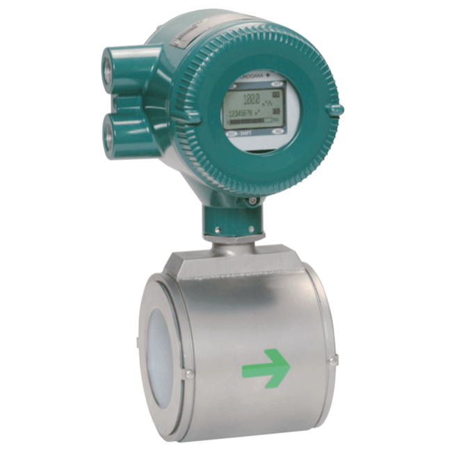
ADMAG AXR Magnetic Flow Meter
Brand: Yokogawa Electric Corporation
The ADMAG AXR two-wire loop-powered magnetic flow meter can be installed in a two-wire system.
The maximum power consumption of the AXR is 0.3W, 40 times less power draw than a traditional magnetic flow meter, resulting in CAPEX and OPEX savings.
The ADMAG AXR is the world's first two-wire magnetic flow meter which employs the fluid noise-free "Dual Frequency Excitation Method," a Yokogawa innovation, achieving excellent stability for instrumentation.
Features- 2-wire Power Loop
- An extra AC power supply is not necessary. 2-wire loop powered performance allows direct connection to DCS I/O card possible, allowing for real cost reductions.
- Reduced CAPEX and OPEX on site.
- Power consumption reduced by 40% compared to a typical 4-wire magnetic flowmeter.
- Annual CO2 emissions can be reduced from approximately 60 kg to 1.2 kg (compared to a standard 4-wire magnetic flowmeter).
- Dual Frequency Performance
- Yokogawa’s unique and advanced excitation method, "Dual Frequency Excitation," achieves stable measurement, zero stability and quick response times. The exclusive technology for stable and reliable measurement on your site.
- Noise Reduction Technology
- Flow noise reduction is further achieved by incorporating smooth mirror finished PFA liners and special surface finished electrodes. This is further enhanced with aligned super high density coils that generate a stronger magnetic field.
- SIL2 Certified
- Yokogawa believes safety should not be an option; it should be standard in all modern products. AXR is the first 2-wire magmeter of SIL2 Safety Integrity Level (IEC 61508) certified. AXR is capable of SIL2 single use and SIL3 redundant use, as standard.
- Parameter Operation
- AXR has magnet switches for parameter setting. Users can access the functions without removing the case cover in hazardous, humid, and dusty environments.
- Adhesion Diagnostic Level Function
- The electrode is one of the most important parts of a magnetic flow meter. Only ADMAG flow meters have "Adhesion Diagnostic Level Function". It diagnoses the condition of electrode surface and indicates the adhesion/coating in 4 levels. Users can change the detection level (threshold) depending on each individual process condition. This allows for predictive maintenance and reduced operating costs.
- Alarm Indication
- ADMAG AXR employs a full-dot matrix LCD indicator. It can display up to 3 lines as required by the user and is available in multiple languages. If an alarm is triggered, a clear message is displayed along with a solution.
- High Accuracy
- The ADMAG AXR performs 0.5% of rate under normal flow rate conditions.
Specifications
Accuracy
- 0.5 % of Rate
Alarm
- 20.5 mA - Process Alarm, Setting Alarm
- 21.6 mA or more - System Alarm, Process Alarm, Setting Alarm
- 3.2 mA or Less - System Alarm, Process Alarm, Setting Alarm
- 3.8 mA - Process Alarm, Setting Alarm
- 4 mA - Process Alarm, Setting Alarm
- Down-Scale: -5 %, 3.2 mA DC or Less - Burn-Out
- Up-Scale: 110 %, 21.6 mA DC or more (Standard) - Burn-Out
Ambient Temperature Range
- 20° ± 5° C (9° F)
- -40° to 55° C (-40° to 131° F) - General-purpose Use
Approvals & Certifications
- Calibration
- Hydrostatic Pressure Test
- Material Certificate
- SIL 2 Capability for Single Flowmeter Use, SIL 3 Capability for Dual Flowmeter Use, IEC 61508: 2000, Part 1 to Part 7
- TÜV (Technischer Uberwachungsverein)
Approvals & Certifications
- ATEX EN 60079-0, EN 60079-1, EN 60079-7, EN 60079-11, EN 60079-31, DEKRA 11-ATEX-0144
- CE
- CSA C22.2 No. 0, C22.2 No. 0.4, C22.2 No. 0.5, C22.2 No. 25, C22.2 No. 30, C22.2 No. 94, C22.2 No. 157, C22.2 No. 61010-1, Class I, Groups A, B, C, D, Class II, Groups E, F, G, Class III
- EMC EN 61326-1 Class A, EN 61326-2-3
- FM FM3600, FM3610, FM3615, FM3810, ANSI / NEMA 250, Explosion-proof for Class I, Div. 1, Groups A, B, C, D, Dust-Ignition-proof for Class II, III, Div. 1, Groups E, F, G
- IECEx IEC 60079-0, IEC 60079-1, IEC 60079-7, IEC 60079-11, IEC 60079-31, Ex d E Ia IIC T6 to T4 Gb
- TIIS Ex d E [ia] IIC T4
BSP Connection
- G 1/2" Female
Cable Length
- 6,562 ft (2,000 metres)
Cable Material
- Polyvinyl Chloride Insulated & Sheathed Portable
Communication
- BRAIN
- HART
Cover Material
- Aluminum Alloy
Current
- 25 mA or Less for 1 Minute at 500 Vac between Power Supply/Digital Output & Functional Grounding
- 3.2 mA (-5 %) or Less - Current Output
- 6 mA or Less for 1 Minute at 100 Vac between Power Supply / Digital Output & Functional Grounding
Diagnostics
- Process, System, Setting Alarm & Warnings (Self Diagnosis)
Diameter
- With No Glands: 0.26" to 0.47" (6.5 to 12 mm)
- With Plastic Glands: 0.24" to 0.47" (6 to 12 mm)
- With Waterproof Glands & Waterproof Glands with Union Joints: 0.41" to 0.45" (10.5 to 11.5 mm)
Display
- Full Dot-Matrix LCD (128 x 64 Pixels)
Distance
- 0.8 Kilometers - Analog I/O Module (For Prosafe-RS)
- 1.4 Kilometers for Analog I/O Module (For Prosafe-RS)
- 6" (15 cm) or more - Distance from Other Power Line
- Up to 2 Kilometers when A CEV Cable is used - Communication Distance (JUXTA, Distributor, I/O Module, Signal Conditioner Card)
Duty Cycle
- 50%
Electrical Connectors
- ANSI 1/2" NPT Female
- ISO M20 x 1.5 Female
- JIS G 1/2" Female
- M4 Screw Terminal
Electrical Protection
- Lightning Protection
Electrical Rating
- 120 mA DC at 30 Vdc
Enclosure Finish
- Corrosion-Resistant Coating
- Epoxy Resin Coating
- High Anti-Corrosion Coating
- Mint Green Paint (Munsell 5.6 BG 3.3/2.9 or its Equivalent) - Coating Color
- Polyurethane Coating
Enclosure, Body Material
- 304 Stainless Steel
- Aluminum Alloy - Converter Material
- Carbon Steel-JIS SPCC Equivalent
Environmental Protection
- IP66
- IP67
- NEMA 4X
Excitation Voltage
- 29 V, Max.
Flange Material
- 304 Stainless Steel
- Carbon Steel (JIS SS400 or SFVC 2A) - Flange & Mini-Flange Material
- JIS SUS430 ASTM 4300 / DIN X6Cr17 / EN 1.4016 Equivalent - Mini Flange
- Stainless Steel-SCS13 - Mini Flange, Pipe
Flange Size - 1-1/2” (DN 40)
- 1-1/2" (DN 40) - 150# ANSI
- 1-1/2" (DN 40) - 300# ANSI
- 1-1/2" (DN 40) - JIS 10K
- 1-1/2" (DN 40) - JIS 20K
- 1-1/2" (DN 40) - PN 10
- 1-1/2" (DN 40) - PN 16
- 1-1/2" (DN 40) - PN 40
Flange Size - 1” (DN 25)
- 1" (DN 25) - 150# ANSI
- 1" (DN 25) - 300# ANSI
- 1" (DN 25) - JIS 10K
- 1" (DN 25) - JIS 20K
- 1" (DN 25) - PN 10
- 1" (DN 25) - PN 16
- 1" (DN 25) - PN 40
Flange Size - 2-1/2” (DN 65)
- 2-1/2" (DN 65) - 150# ANSI
- 2-1/2" (DN 65) - 300# ANSI
- 2-1/2" (DN 65) - JIS 10K
- 2-1/2" (DN 65) - JIS 20K
- 2-1/2" (DN 65) - PN 10
- 2-1/2" (DN 65) - PN 16
- 2-1/2" (DN 65) - PN 40
Flange Size - 2” (DN 50)
- 2" (DN 50) - 150# ANSI
- 2" (DN 50) - 300# ANSI
- 2" (DN 50) - JIS 10K
- 2" (DN 50) - JIS 20K
- 2" (DN 50) - PN 10
- 2" (DN 50) - PN 16
- 2" (DN 50) - PN 40
Flange Size - 3” (DN 80)
- 3" (DN 80) - 150# ANSI
- 3" (DN 80) - 300# ANSI
- 3" (DN 80) - JIS 10K
- 3" (DN 80) - JIS 20K
- 3" (DN 80) - PN 10
- 3" (DN 80) - PN 16
- 3" (DN 80) - PN 40
Flange Size - 4” (DN 100)
- 4" (DN 100) - 150# ANSI
- 4" (DN 100) - 300# ANSI
- 4" (DN 100) - JIS 10K
- 4" (DN 100) - JIS 20K
- 4" (DN 100) - PN 10
- 4" (DN 100) - PN 16
- 4" (DN 100) - PN 40
Flange Size - 6” (DN 150)
- 6" (DN 150) - 150# ANSI
- 6" (DN 150) - 300# ANSI
- 6" (DN 150) - JIS 10K
- 6" (DN 150) - JIS 20K
- 6" (DN 150) - PN 10
- 6" (DN 150) - PN 16
- 6" (DN 150) - PN 40
Flange Size - 8” (DN 200)
- 8" (DN 200) - 150# ANSI
- 8" (DN 200) - 300# ANSI
- 8" (DN 200) - JIS 10K
- 8" (DN 200) - JIS 20K
- 8" (DN 200) - PN 10
- 8" (DN 200) - PN 16
- 8" (DN 200) - PN 40
Flow Rate
- 0 to 18,850 LPM (0 to 4,979 gpm) - Max.
- 0 to 565.5 LPM (0 to 149.4 gpm) - min. Span Flow Rate (1 ft/sec)
Fluid
- Gas
- Liquid
Gasket Material
- Chloroprene Rubber
- Fluororubber (Acid Resistant & Alkali Resistant) for PVC Pipes (Viton)
- PTFE-Sheathed Non-Asbestos
Humidity
- 0 to 100 % - Ambient Humidity
Input Impedance
- 10 kΩ or more at 2.4 kHz - Communicating Device
Insulation Resistance
- 100 MΩ or more at 50 Vdc between Power Supply / Digital Output & Functional Grounding
- 20 MΩ or more at 100 Vdc between Power Supply/Digital Output & Functional Grounding
Load
- 0.22 µF or Less - Load Capacitance
- 3.3 MH - Load Inductance
Maximum Current
- 17 mA - Intrinsically Safety Circuit
- 600 A (8/20 μs) - Allowable Current
Maximum Voltage
- 14 V - Intrinsically Safety Circuit
Mounting
- M4 Screw
Mounting Position
- Vertical
NPT Connection
- 1/2" NPT Female
Nut & Bolt Material
- Carbon Steel
Operating Temperature
- -20° to 55° C (-4° to 131° F) - Indicator Operating Range
Output
- 0-2 Vdc - Low Level
- 10.4 mA Current Output - During Zero Adjustment (450 seconds)
- 2 Vdc, 120 mA - Max.
- 3.8 - 20.5 mA ( - 1.25 to 103.13 %)
- 30 Vdc, Max.
- 4-20 mA DC, 2-Wire System - Current Output
Output Format
- Alarm Output
- Current Output
- Pulse Output
Power
- 0.12 W - Max.
Power Supply
- 14.7 to 42 Vdc, 2-Wire System - Integral Flowmeter Operating Voltage Range
- 42 Vdc, Max.
Process Connection Style
- Wafer
Process Temperature
- -40° to 130° C (-40° to 266° F)
Pulse Range
- 0.0001 to 10,000 Pulse/second - Pulse Output Rate
- 0.05 to 100 ms - Pulse Width
Repeatability
- ± 0.2 % of Rate (When the Flow Velocity is 1.5 m/sec Toward 2 m/sec of Setting Span)
Resistance
- 10 ohms or Less - Grounding Resistance when Lightning Protector is Used
- 100 ohms or Less - Grounding Resistance
- 250 to 600 ohms (Including Cable Resistance) - Load Resistance
Ring Material
- 316 Stainless Steel - Grounding Ring (Plate Typical)
- Hastelloy C-276 - Grounding Ring (Plate Typical)
- Stainless Steel-JIS SUS316L or ASTM 316L (AISI 316L Stainless Steel / EN 1.4404 Equivalent) - Grounding Ring (Plate Typical)
Rotation
- 180° Rotated Converter to Change the Direction of Electrical Connection
- 90° Rotated Converter to Change the Direction of Electrical Connection
- -90° Rotated Converter to Change the Direction of Electrical Connection
Size
- 1 to 8" (25 to 200 mm): 10 μS/cm or Larger - Fluid Conductivity
- 1" to 4" (25 to 100 mm) - Wafer & Flange Typical
Supply Voltage
- 14.7-32 Vdc for Lightning Protector
- 14.7-42 Vdc for General-purpose Use & Explosion-proof Typical
- 20.6-42 Vdc - Communication Requirement for BRAIN, HART
- 250 Vac - Electrode Circuit, Allowable Voltage (50/60 Hz)
- 250 Vdc - Allowable Voltage
Switch Quantity
- 4 Magnet Switches (Including Push Switches) - Operational Switch
Temperature Range
- -20° to 130° C (-4° to 265° F) - Fluid Temperature
Time Constant
- 1 to 200 seconds (63 % Response) - Damping Time Constant
- 5 seconds - Default Damping Time Constant
Vibration
- 9.8 m/sec² or Less (500 Hz or Less)
Wetted Materials
- 316 Stainless Steel - Grounding Ring/Grounding Electrode
- 316L Stainless Steel - Electrode
- Fluorocarbon PFA Lining
- Hastelloy C-276 Equivalent - Electrode
- Platinum Iridium - Electrode
- Tantalum - Electrode
Wiring
- 0.5 to 1.5 mm² - Stranded Wire: Nominal Cross Section
- 0.5 to 2.5 mm² - Single Wire: Nominal Cross Section
Documentation
Product Manuals
Brochure
- Brochure A pdf 3.1 MB
- Brochure B pdf 2.7 MB
- Brochure C pdf 4.5 MB
- Brochure D pdf 7.3 MB
- Brochure E pdf 1.6 MB
- Brochure F pdf 1.4 MB
- Brochure G pdf 1.6 MB
- Brochure H pdf 934 KB
- Brochure I pdf 1.2 MB
- Brochure J pdf 767 KB
- Brochure K pdf 960 KB
- Brochure L pdf 1.3 MB
- Brochure M pdf 1.2 MB
- Brochure N pdf 1.4 MB
- Brochure O pdf 1.2 MB
- Brochure P pdf 769 KB